Squeeze-in underground diaphragm wall gapless steering device

An underground diaphragm wall and steering device technology, which is applied to sheet pile walls, buildings, and foundation structure engineering, can solve the problems of high cost, affecting the quality of the wall, and poor water-stop effect, so as to save cost and reduce hinge friction. The effect of resistive area

Active Publication Date: 2017-01-18
QINGDAO JINGLI ENG +1
View PDF3 Cites 0 Cited by
  • Summary
  • Abstract
  • Description
  • Claims
  • Application Information

AI Technical Summary

Problems solved by technology

[0002] At present, the walking systems of all hydraulic static pile drivers (hereinafter referred to as static pile drivers) at home and abroad are all walking systems. When turning or moving in a straight line during the pile pressing process, the piles are cut off from the surface or directly pressed against the top of the piles. The construction technology of the squeeze-in underground diaphragm wall (hereinafter referred to as the squeeze-in floor wall) requires at least one wall-forming device that cannot be pulled out of the ground before the construction of the squeeze-in floor wall is completed, otherwise, it will be damaged due to the unit wall section. The incoherent mechanical connection between them will cause water seepage, which will affect the quality of the wall; moreover, the wall-forming device is expensive and can be used repeatedly.
The existing method is to implement the inner and outer multi-layered overlapping corner walls according to the corresponding angles at the corners of the ground wall to seal the interface to achieve the purpose of waterproofing and anti-seepage; practice has proved that the sealing effect of the overlapping sealing method at the corners of the extruded ground wall is not good. Especially in the saturated water soft soil layer or complex soil layer, the waterproof effect of the overlapping corner wall basically fails to meet the technical requirements for waterproof and anti-seepage

Method used


Image

  • Squeeze-in underground diaphragm wall gapless steering device
  • Squeeze-in underground diaphragm wall gapless steering device
  • Squeeze-in underground diaphragm wall gapless steering device

Examples


Embodiment Construction

[0032] The present invention will be further described below in conjunction with the accompanying drawings and embodiments.

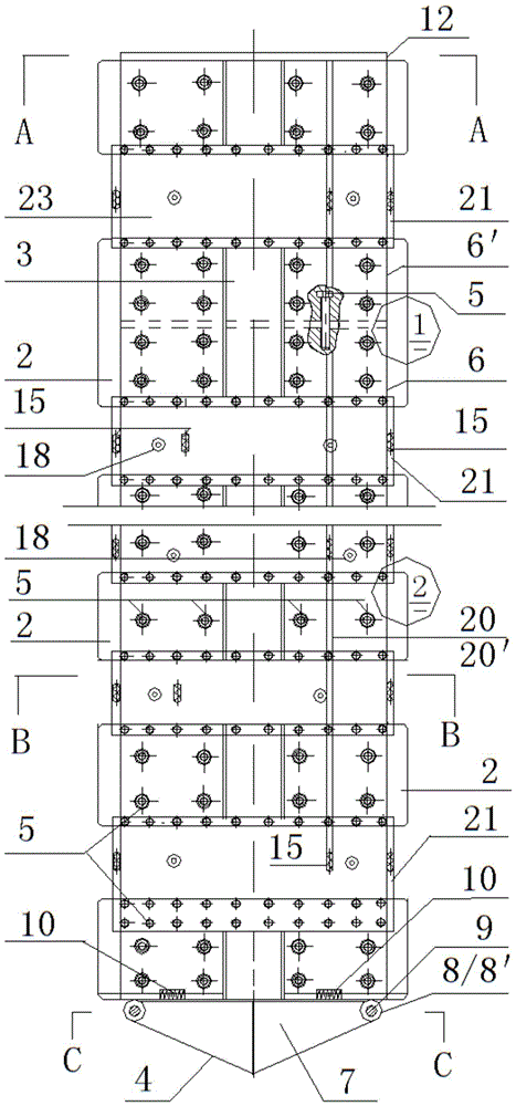
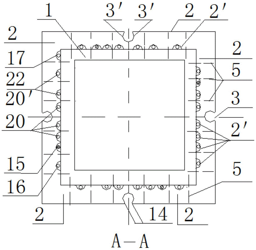
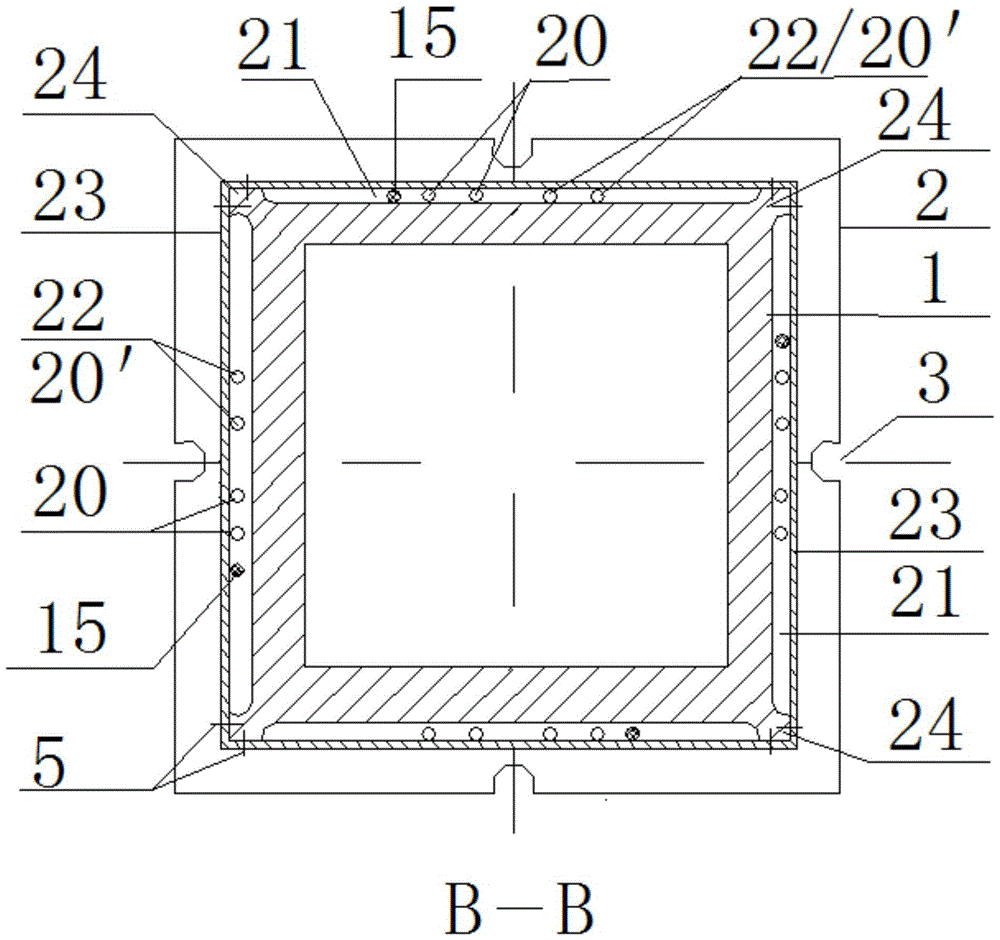
[0033] Such as figure 1 , Figure 6 and Figure 11 As shown, the squeeze-in underground continuous wall gapless steering device of the present invention includes a housing, a vibration cooling device and a rotating device. Such as Figure 1 to Figure 5 As shown, the housing is mainly composed of an inner housing 1, an outer housing 2, a socket 3, and a valve disc. The outer housing 2 is rectangular in shape, and the inner housing 1 is divided into rectangular or circular. In order to meet the requirements of different geometric dimensions of the underground diaphragm wall, the geometric dimensions of the shell are also divided into various specifications. Such as Figure 1 to Figure 3As shown, the rectangular inner shell 1 is a thick-walled hollow rectangular tube with an inner diameter ranging from 200 to 1000 mm and an outer diameter ranging from...


PUM


Abstract

The invention relates to a squeezing type underground continuous wall gapless steering device, and belongs to the technical field of underground space development static force extrusion. The problem that in the construction process of an existing static pressure underground continuous wall, steering is incoherent, water seepage happens, and the wall forming quality is affected is solved. The squeezing type underground continuous wall gapless steering device comprises a shell, a vibration cooling device and a rotating device, the vibration cooling device is located in the shell, and the rotating device is arranged at the upper end of the shell. The squeezing type underground continuous wall gapless steering device is applied to the axis angle change of a squeezing type underground continuous wall and steering with the angle larger than or smaller than 90 degrees.

Description

technical field [0001] The invention relates to a squeeze-in type underground continuous wall gapless steering device, which belongs to the technical field of static squeeze-in for underground space development. Background technique [0002] At present, the walking systems of all hydraulic static pile drivers (hereinafter referred to as static pile drivers) at home and abroad are all walking systems. When turning or moving in a straight line during the pile pressing process, the piles are cut off from the surface or directly pressed against the top of the piles. The construction technology of the squeeze-in underground diaphragm wall (hereinafter referred to as the squeeze-in floor wall) requires at least one wall-forming device that cannot be pulled out of the ground before the construction of the squeeze-in floor wall is completed, otherwise, it will be damaged due to the unit wall section. The incoherent mechanical connection between them will cause water seepage, which w...

Claims


Application Information

Patent Timeline
Patent Type & Authority Patents(China)
IPC IPC(8): E02D7/00E02D5/68E02D5/18E02D7/18E02D7/26E02D15/04
Inventor 欧阳牧虎欧阳蓓蓓欧阳甘霖赵婉宇
Owner QINGDAO JINGLI ENG
Why Eureka
Try Eureka