Hydraulic control valve group, hydraulic system and operation machine

A technology of hydraulic control valve and hydraulic system, which is applied to the safety of fluid pressure actuation system, components of fluid pressure actuation system, mechanical equipment, etc., can solve the problems of pumping continuity, reduce pumping efficiency, etc., and reduce jitter , Reduce the effect of system shock and pressure peak reduction

Pending Publication Date: 2022-01-07
SANY AUTOMOBILE MFG CO LTD
View PDF0 Cites 1 Cited by
  • Summary
  • Abstract
  • Description
  • Claims
  • Application Information

AI Technical Summary

Problems solved by technology

But this will reduce the pumping efficiency, and will also cause a gap in the pumping pressure of the system, which will have a negative impact on the continuity of pumping

Method used


Image

  • Hydraulic control valve group, hydraulic system and operation machine

Examples


Embodiment Construction

[0031] In order to make the purpose, technical solutions and advantages of the present invention clearer, the technical solutions in the present invention will be clearly and completely described below in conjunction with the accompanying drawings in the present invention. Obviously, the described embodiments are part of the embodiments of the present invention , but not all examples. Based on the embodiments of the present invention, all other embodiments obtained by persons of ordinary skill in the art without creative efforts fall within the protection scope of the present invention.

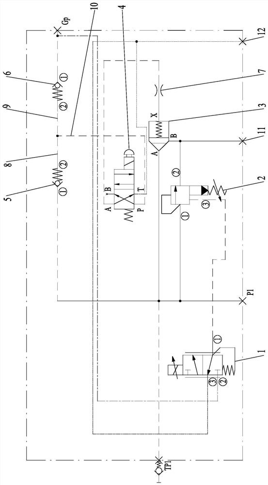
[0032] Combine below figure 1 The hydraulic control valve group of the present invention is described.

[0033] Such as figure 1 As shown, the embodiment of the present invention provides a hydraulic control valve group, including a proportional valve 1 and a pressure regulating valve 2 . Specifically, according to the pressure of the main oil circuit of the main valve, the oil outlet (por...


PUM


Abstract

The invention provides a hydraulic control valve group, a hydraulic system and an operation machine. The hydraulic control valve group comprises a proportional valve and a pressure regulating valve. The pressure regulating valve comprises an oil inlet connected with a main oil way of a main valve, an oil outlet used for oil return and a remote pressure regulating opening connected with an oil outlet of the proportional valve. According to the pressure of the main oil way of the main valve, the oil outlet of the proportional valve outputs corresponding control flow. The opening degree of the valve opening of the pressure regulating valve is regulated according to the control flow output by the proportional valve. In this way, a safety pressure value is preset for the pressure regulating valve, and during working, the control flow of the oil outlet of the proportional valve is controlled according to the pressure of the main oil way of the main valve and transmitted to the remote pressure regulating opening. Then real-time pilot control pressure required by the pressure regulating valve is calculated according to the control flow, and the opening degree of the valve opening of the pressure regulating valve is regulated, so that the control pressure of the pressure regulating valve is reduced in proportion, the pressure peak value of a system during reversing is reduced, system impact is reduced, shaking caused by the impact is relieved, and the pumping efficiency and the pumping continuity are not lost.

Description

technical field [0001] The invention relates to the technical field of engineering machinery, in particular to a hydraulic control valve group, a hydraulic system and an operating machine. Background technique [0002] The current overload protection scheme for the concrete pumping hydraulic system is to set a system overflow pressure higher than the cut-off pressure of the main oil pump in the system, and the pressure value is as high as 35MPa and above. Therefore, the system often works under high pressure and large flow, and the peak value of the pressure shock at the moment of each reversing will also reach the set system overflow pressure. Such a high pressure shock not only increases the noise generated by the commutation, seriously affects the stability and service life of the system components, but also brings greater vibration to the whole machine. [0003] In order to reduce the impact of reversing, the existing technical solution is to reduce the impact pressure ...

Claims


Application Information

Patent Timeline
Patent Type & Authority Applications(China)
IPC IPC(8): F15B13/02F15B13/044F15B20/00F15B21/00
CPCF15B13/02F15B13/027F15B13/044F15B20/007F15B21/008F15B2013/004
Inventor 李俊杨敏胡涛
Owner SANY AUTOMOBILE MFG CO LTD
Why Eureka
Try Eureka