

Single-piston stroke inductive type resistance change damping structure
A technology of stroke induction and resistance change, which is applied in the direction of springs, shock absorbers, spring/shock absorbers, etc., can solve the problems of limited range of use, high cost, difficulty in debugging and maintenance, and achieve the effect of variable damping
- Summary
- Abstract
- Description
- Claims
- Application Information
AI Technical Summary
Problems solved by technology
Method used
Image

Examples
Embodiment 1
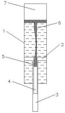
[0022] Embodiment 1: Single-piston stroke-inductive resistance change damping structure (see attached figure 1 ), including a cylinder 1, a piston 2 is arranged in the cylinder 1, a piston rod 3 is arranged in the piston 2, a through hole 4 with an opening 5 is arranged on the piston rod 3, and the through hole 4 A variable-diameter damping rod 6 is arranged inside, the length of the variable-diameter damping rod 6 is greater than the depth of the through hole 4, the diameter of the variable-diameter damping rod 6 gradually changes through a smooth arc, and the upper end of the cylinder 1 is provided with a seal The air chamber 7, the air-sealed chamber 7 is fixedly connected with the cylinder body 1 .
[0023] The smooth arc of the damping rod is excessive and gradual, so that the damping changes smoothly and the stability is high. By changing the gap between the variable-diameter damping rod arranged in the through hole and the through hole and the opening on the through hol...
Embodiment 2
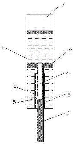
[0024] Embodiment 2: Single-piston stroke-inductive resistance change damping structure (see attached figure 2 ), including a cylinder body 1, a piston 2 is arranged in the cylinder body 1, a piston rod 3 is arranged in the piston 2, a through hole 4 with an opening 5 is arranged on the piston rod 3, and a 3. A variable damping outer tube 8 is provided. The variable damping outer tube 8 is sleeved on the outside of the piston rod 3. The variable damping outer tube 8 is fixedly connected to the cylinder body 1. The variable damping outer tube 8 is provided with a row of damping holes 9, the distance between the damping holes 9 is smaller than the maximum diameter of the opening 5, the damping holes 9 are arranged longitudinally on the variable damping outer tube 8, and the upper end of the cylinder 1 is provided with a gas seal Cavity 7, the air-sealed cavity 7 is fixedly connected with the cylinder body 1.
[0025] By changing the positions of the damping hole and the upper ...
Embodiment 3
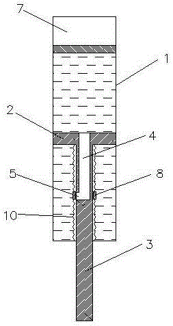
[0027] Embodiment 3: Single-piston stroke-inductive resistance change damping structure (see attached image 3 ), including a cylinder 1, a piston 2 is arranged in the cylinder 1, a piston rod 3 is arranged in the piston 2, a through hole 4 with an opening 5 is arranged on the piston rod 3, and the variable damping Both ends of the outer tube 8 are provided with damping springs 10, the damping spring 10 at the upper end of the variable damping outer tube 8 is fixedly connected with the piston 3, and the damping spring 10 at the lower end of the variable damping outer tube 8 is fixed to the cylinder body 1 Connection, the length of the variable damping outer tube 8 is greater than or equal to the maximum diameter of the opening 5, the upper end of the cylinder 1 is provided with an air sealing chamber 7, and the air sealing chamber 7 is fixedly connected with the cylinder 1.
[0028] When the piston compresses and moves, the relative position of the variable damping outer tube ...
PUM
 Abstract
Description
Claims
Application Information