Right-angled electromagnetic valve based on pilot structure

A right-angle, solenoid valve technology, applied in valve details, valve device, valve operation/release device, etc., can solve problems such as slow speed and large opening torque, to ensure the reliability of sealing, reduce opening force, avoid The effect of wasting resources

Inactive Publication Date: 2015-12-23
UNIV OF JINAN
View PDF9 Cites 1 Cited by
  • Summary
  • Abstract
  • Description
  • Claims
  • Application Information

AI Technical Summary

Problems solved by technology

[0004] The patent of the present invention provides a right-angle solenoid valve based on the pilot structu

Method used


Image

  • Right-angled electromagnetic valve based on pilot structure
  • Right-angled electromagnetic valve based on pilot structure
  • Right-angled electromagnetic valve based on pilot structure

Examples


Example Embodiment

[0039] Examples:

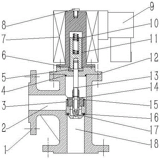
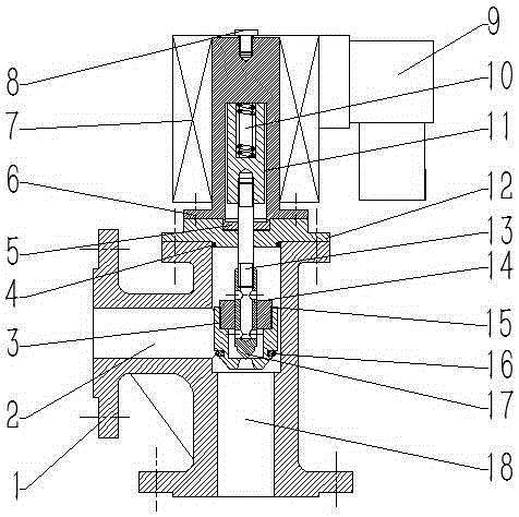
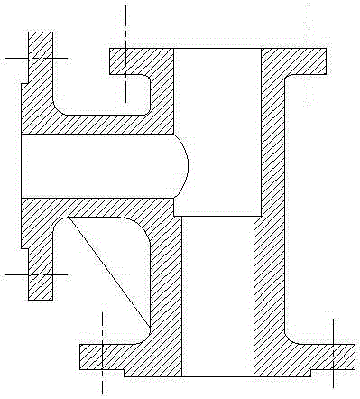
[0040] Such as figure 1 , figure 2 , image 3 As shown, this embodiment includes a valve body 1, a material inlet 2, a valve core 3, a valve cover sealing ring 4, a pressure plate 5, a static armature 6, an electromagnetic coil 7, a fixing bolt 8, a controller 9, a return spring 10, and a movable Armature 11, valve cover 12, pilot rod 13, valve core closing plug 14, valve core closing plug sealing ring 15, valve core sealing ring 16, pilot valve core 17, discharge port 18; valve body 1 is fixedly installed above the valve Cover 12, the top of the valve cover 12 is fixedly installed with a static armature 6, the static armature 6 is fixedly installed with a solenoid 7 on the outside, and the solenoid 7 is fixedly connected with a controller 9; the static armature 6 is installed with a fixed clearance fit The movable armature 11 is fixedly fitted with a return spring 10 between the movable armature 11 and the static armature 6, and a pilot rod 13 is screwed und...


PUM


Abstract

The invention belongs to the technical field of valve equipment, and in particular, relates to a right-angled electromagnetic valve based on a pilot structure. The right-angled electromagnetic valve comprises a valve body, wherein a valve cover is fixedly mounted above the valve body; a static gag bit is fixedly mounted above the valve cover; the external of the static gag bit is fixed and matched with an electromagnetic coil; the electromagnetic coil is fixedly connected with a controller; the internal of the static gag bit is fixed and matched with a movable gag bit at intervals; a return spring is matched and mounted between the movable gag bit and the static gag bit; a pilot rod is in threaded connection below the movable gag bit; the pilot rod and the valve cover are matched and provided with a pressure plate; the other end of the pilot rod is in threaded connection with a pilot valve core; the external of the pilot valve core is matched and provided with a valve core closing plug; the external of the valve core closing plug is in threaded connection with a valve core; a feed port is formed in one side, far from the valve core, of the valve body; and a discharge port is formed below the valve core.

Description

technical field [0001] The patent of the invention belongs to the technical field of valve equipment, and in particular relates to a right-angle solenoid valve based on a pilot structure. Background technique [0002] Valves are used in fluid systems to control the direction of fluid, pressure 1. The flow device is a device that makes the medium (liquid, gas, powder) in the piping and equipment flow or stops and can control its flow. The control of the valve can adopt a variety of transmission methods, such as manual, electric, hydraulic, pneumatic, turbine, electromagnetic, electro-hydraulic, electro-hydraulic, gas-hydraulic, spur gear, bevel gear drive, etc.; can be driven by pressure, temperature Under the action of sensing signals in other forms, it acts according to predetermined requirements, or simply opens or closes without relying on sensing signals. The valve relies on driving or automatic mechanism to make the opening and closing parts lift, slide, swing or rotat...

Claims


Application Information

Patent Timeline
IPC IPC(8): F16K31/06F16K41/00
CPCF16K31/0655F16K41/00
Inventor 昃向博张孟杰李国平安延涛
Owner UNIV OF JINAN
Why Eureka
Try Eureka