
Solar heat energy receiving device in desert area

A receiving device, desert technology, applied in the field of renewable energy utilization, can solve problems such as lack of

Inactive Publication Date: 2015-12-23
戚荣生
View PDF11 Cites 0 Cited by
  • Summary
  • Abstract
  • Description
  • Claims
  • Application Information

AI Technical Summary

Problems solved by technology

And in the prior art, also lack this kind of technology

Method used


Image

  • Solar heat energy receiving device in desert area
  • Solar heat energy receiving device in desert area
  • Solar heat energy receiving device in desert area

Examples


Embodiment 1

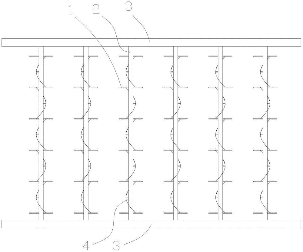
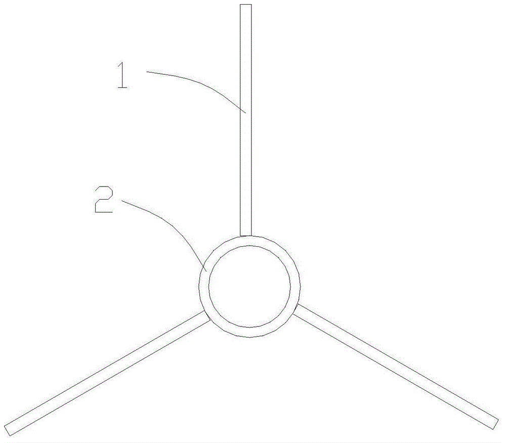
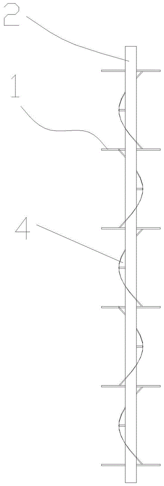
[0022] Such as Figure 1-2 As shown, a solar heat receiving device in a desert area includes a heat exchange tube 2 buried in the desert. The outer tube wall of the heat exchange tube 2 is provided with spirally surrounded fins 4, and the outer tube wall of the heat exchange tube 2 is A circle of heat conducting plates 1 is set every 20-30 cm, and three heat conducting plates 1 are evenly formed in a circle; multiple heat exchange tubes 2 are arranged in parallel, and the two ends of the multiple heat exchange tubes 2 are respectively connected by a confluence pipe 3, The confluence pipe 3 at one end is the liquid inlet end, and the confluence pipe 3 at the other end is the liquid discharge end.

Embodiment 2

[0024] Such as Figure 3-5 As shown, a solar heat receiving device in a desert area includes a heat exchange tube 2 buried in the desert. The outer tube wall of the heat exchange tube 2 is provided with spirally surrounded fins 4, and the outer tube wall of the heat exchange tube 2 is A heat conduction plate 1 is arranged in a circle every 20-30 cm, and three heat conduction plates 1 are evenly formed in a circle; the heat exchange tube 2 is spirally coiled, and one end of the heat exchange tube 2 is a liquid inlet end, and the other end is a liquid outlet end. The surface of the heat conducting plate 1 is provided with wavy protrusions 5 .


PUM


Abstract

The invention provides a solar heat energy receiving device in a desert area, and relates to the technical field of utilization of renewable energy sources. The solar heat energy receiving device in the desert area comprises heat-exchanging pipes buried in the desert. Fins are spirally arranged around the outer pipe wall of each heat-exchanging pipe. A circle of heat-conducting plates are arranged every 20-30 cm on the outer pipe wall of each heat-exchanging pipe. Each circle includes at least three heat-conducting plates uniformly arranged in a surrounding mode. According to the solar heat energy receiving device in the desert area, the heat energy in the desert can be collected to be used, and the heat energy is conveyed out through heat-exchanging media. The heat energy receiving device can fix sand in the desert at the same time of conducting heat exchange, so that the situation that under the action of wind, sand moves, and the heat energy receiving device buried in the sand is directly exposed is avoided.

Description

technical field [0001] The invention relates to the technical field of renewable energy utilization, in particular to a solar heat receiving device in a desert area. Background technique [0002] Entering the 21st century, the shortage of petrochemical energy and the lack of coal resources have caused the shortage of power resources at the same time, and the three major emissions of thermal power generation, vehicle exhaust emissions and industrial pollution all over the place have contributed to the sharp deterioration of the air environment. It has seriously threatened the security of national energy and the quality of the air environment on which citizens depend. This situation has reached a point where it must be resolved. [0003] Therefore, making full use of renewable solar energy, wind resources and underground energy, and converting them into clean and environmentally friendly new energy has become a top priority for all citizens. But the actual situation is not o...

Claims


Application Information

Patent Timeline
Patent Type & Authority Applications(China)
IPC IPC(8): F24J3/08
CPCY02E10/10
Inventor 戚荣生
Owner 戚荣生
Learn More