
Fluid Distribution Collectors and Systems

A fluid distribution and collection system technology, applied in heat exchanger shells, lighting and heating equipment, heat exchange equipment, etc., can solve problems such as uneven flow distribution, equipment burnout, system stability reduction, etc., to achieve strong scalability , Easy installation and compact structure

Active Publication Date: 2017-06-06
SHANGHAI SATELLITE ENG INST
View PDF5 Cites 0 Cited by
  • Summary
  • Abstract
  • Description
  • Claims
  • Application Information

AI Technical Summary

Problems solved by technology

[0003] The micro-channel parallel flow heat exchanger can significantly improve the heat dissipation capacity, and has the advantages of small size, light weight, and compact structure. However, since the heat exchange medium flows in parallel in parallel channels, the flow distribution in each channel is uneven. One of the main factors affecting the performance of parallel flow evaporator
Pacio et al. used numerical methods to study parallel flow evaporators, and believed that uneven flow distribution would seriously affect the heat transfer performance of the heat exchanger.
[0004] However, the capacity of the current fluid flow distribution device is quite limited, mainly focusing on the distribution of less than 6-8 channels. For more parallel channels, it is difficult to achieve uniform distribution of each channel, which seriously limits the microchannel parallel flow heat transfer. Therefore, for heat dissipation surfaces with similar aspect ratios, the number of flows of the working fluid in the heat exchanger can only be increased, which will inevitably increase the flow resistance of the working fluid in the heat exchanger, and also due to the The temperature difference relationship between the upstream and downstream of the flow leads to uneven temperature on the heat dissipation surface, and the purpose of heat dissipation cannot be achieved for heating equipment with special temperature difference requirements
[0005] For the annular heat source surface, the single inlet / outlet structure will cause the fluid to form an elliptical flow around the annular cylinder, and then form a large stagnation area at both ends, which will seriously affect the heat transfer and even cause equipment failure. partial burn
At present, the commonly used method is to increase the fluid flow rate and drive the flow at both ends by increasing the overall flow velocity, but it cannot fundamentally solve the problem of the stagnation area, and it also brings about the problem of excessive flow resistance, resulting in a waste of energy resources.
Or set up complex distribution pipelines at the entrance and exit, but this will cause the entire system to be bulky, which cannot be used in some systems with limited space, and the stability of the system will be greatly reduced due to the increase in the risk of leakage due to the addition of many joints

Method used


Image

  • Fluid Distribution Collectors and Systems
  • Fluid Distribution Collectors and Systems
  • Fluid Distribution Collectors and Systems

Examples


Embodiment Construction

[0041] The present invention will be described in detail below in conjunction with specific embodiments. The following examples will help those skilled in the art to further understand the present invention, but do not limit the present invention in any form. It should be noted that those skilled in the art can make several modifications and improvements without departing from the concept of the present invention. These all belong to the protection scope of the present invention.

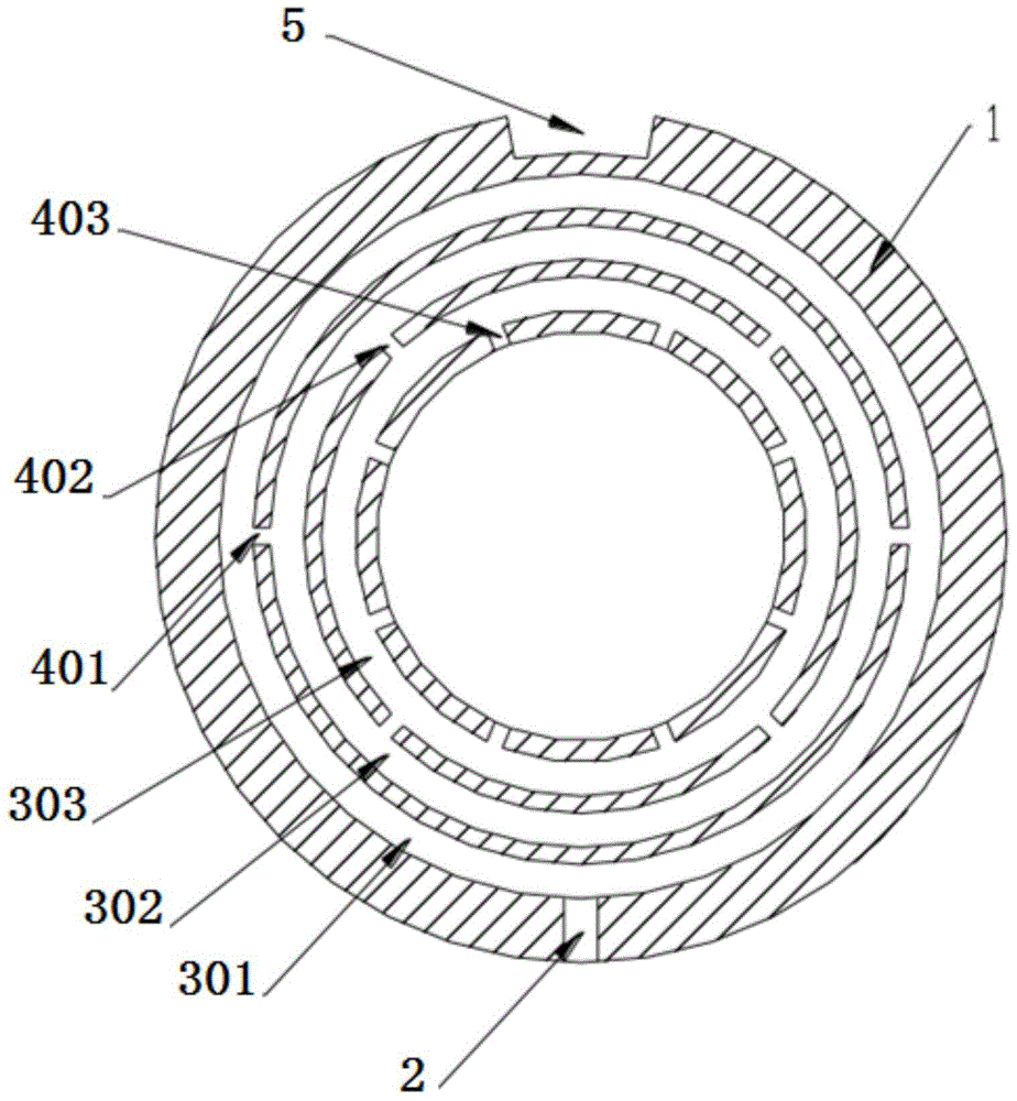
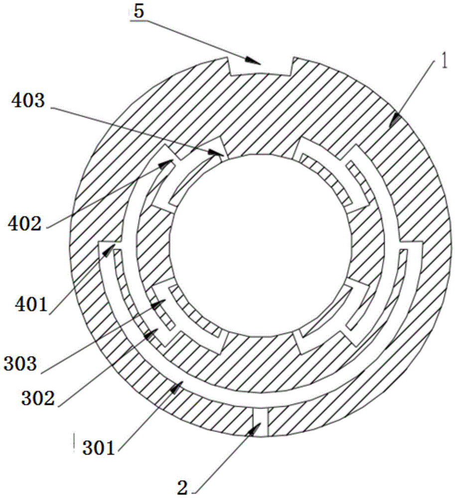
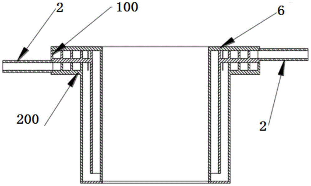
[0042] In this embodiment, the fluid distribution collector provided by the present invention includes a distribution collection body 1 and a cover plate 6; wherein, the cover plate 6 fits on one end surface of the distribution collection body 1; the distribution collection body 1. There are multi-layer nested flow channels, fluid inlets and outlets 2 and confluence channels. Openings are provided between adjacent layers of flow channels and communicated through the openings; the outermost flow cha...


PUM


Abstract

The invention provides a fluid allocation collector and a system. The fluid allocation collector comprises an allocation collection body and a cover plate. The cover plate is attached to the end face of one end of the allocation collection body. The allocation collection body is provided with a plurality of layers embedded flowing channels, a fluid outlet / inlet and a confluent passageway. An opening is formed between every two adjacent layers of flowing channels. The flowing channels are communicated through the openings. The flowing channel on the outermost layer is communicated with the fluid outlet / inlet. The flowing channel on the innermost layer is communicated with the confluent passageway. The fluid allocation collector is suitable for allocating fluid on inlets of annular cylindrical face flowing channels or multiple-channel parallel flowing channels and collecting fluid on outlets of the annular cylindrical face flowing channels or the multiple-channel parallel flowing channels; and it can be guaranteed that the angles of the annular cylindrical face flowing channels or the structures of channels of the multiple-channel parallel flowing channels are the same through geometric construction, and therefore it can be guaranteed that flowing resistance of the fluid allocation collector is the same, and fluid in the whole flowing area can be evenly distributed.

Description

technical field [0001] The present invention relates to a distribution collector, in particular to a fluid distribution collector and system. Background technique [0002] In recent years, with the development of high and new technologies such as aerospace technology, information and electronic technology, MEMS technology, biotechnology and life sciences, there are prominent features such as miniaturization, compactness of space scale, and complexity of structure and conditions, which make people have to Considering the miniaturization of the heat and mass transfer process, the complexity of the structure and conditions, micro-scale flow and heat transfer have become one of the theoretical and technical foundations of modern high-tech. [0003] The micro-channel parallel flow heat exchanger can significantly improve the heat dissipation capacity, and has the advantages of small size, light weight, and compact structure. However, since the heat exchange medium flows in parall...

Claims


Application Information

Patent Timeline
Patent Type & Authority Patents(China)
IPC IPC(8): F28F9/22
Inventor 刘冈云陈彬彬徐涛陈钢杜忠选张翔
Owner SHANGHAI SATELLITE ENG INST
Learn More