Optical cable dynamic friction coefficient test device and method

A technology for the coefficient of kinetic friction and testing equipment, which is used in measuring devices, instruments, and mechanical devices, etc. It can solve the problems of not being able to make more detailed plans for optical cables through pipes, users not being able to accurately know the optical cables, and unable to refer to the coefficient of kinetic friction. Accurate parameters, accurate coefficient of kinetic friction and uniform force

Inactive Publication Date: 2015-12-23
FENGHUO COMM SCI & TECH CO LTD
View PDF6 Cites 10 Cited by
  • Summary
  • Abstract
  • Description
  • Claims
  • Application Information

AI Technical Summary

Problems solved by technology

However, in the existing technology, the dynamic friction coefficient of the optical cable is based on the data provided by the supplier, and there is no equipment for testing the actual dynamic friction coefficient of the optical cable. With reference to the actual coefficient of dynamic friction, it is not possible to formulate a more detailed plan for optical cable penetration

Method used


Image

  • Optical cable dynamic friction coefficient test device and method
  • Optical cable dynamic friction coefficient test device and method

Examples


Embodiment Construction

[0024] The present invention will be described in further detail below in conjunction with the accompanying drawings and embodiments.

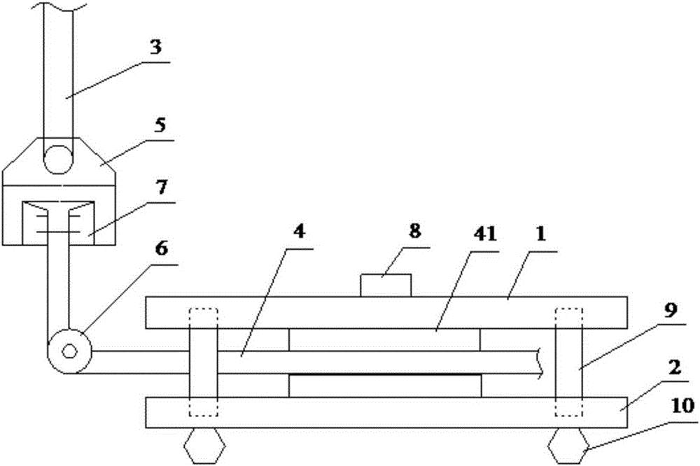
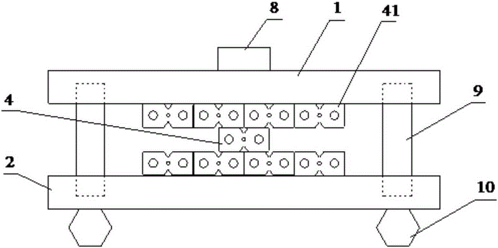
[0025] Such as figure 1 As shown, the optical cable dynamic friction coefficient testing equipment of the present invention comprises an upper steel plate 1 and a lower steel plate 2, and the four corners of the top surface of the lower steel plate 2 are respectively provided with concave holes, and each concave hole is inserted with a support rod 9, and the upper steel plate 1 The four corners of the bottom surface are also provided with concave holes, which are used to accommodate the top of each support rod. Therefore, the upper steel plate 1 and the lower steel plate 2 are supported by the support rod 9, and the four corners of the bottom surface of the lower steel plate 2 are respectively provided with A pad 10 of the same height ensures that the stainless steel plate does not tilt. An optical cable 4 to be tested is arranged horizontall...


PUM

PropertyMeasurementUnit
diameteraaaaaaaaaa
lengthaaaaaaaaaa

Abstract

An optical cable dynamic friction coefficient test device relates to the field of test of friction coefficient, and comprises an upper steel plate and a lower steel plate; support rods support between the two steel plates; an optical cable to be tested is horizontally placed between the two steel plates; a weight is arranged at the center of the top wall of the upper steel plate; one pulling draw bar is vertically arranged above one side of the two steel plates; the lower end of the puling draw bar is provided with a clamp for clamping the optical cable to be tested; a fixed pulley is arranged right below the clamp; one end of the optical cable to be tested bypasses the fixed pulley and is connected to the clamp, and the fixed pulley and the horizontally placed part of the optical cable to be tested are positioned at the same plane, and the upper end of the pulling draw bar is connected to a universal tester. The optical cable dynamic friction coefficient test device can stably effectively test the dynamic friction coefficient of the optical cable, and provide accurate reference values for a user.

Description

technical field [0001] The invention relates to the field of friction coefficient testing, in particular to an optical cable dynamic friction coefficient testing device and method. Background technique [0002] As the development of FTTH (Fiber To The Home, fiber to the home) is accelerating day by day in China, the three major operators are all increasing their efforts in broadband construction. In order to make full use of the existing ducts, it is necessary to implement additional fiber optic cable laying. The additional fiber optic cable needs to be installed in the existing duct by means of traction installation. Due to greater friction between the additional optical cable and the existing optical cable in the duct, it is very unfavorable for the additional optical cable to pass through the duct. [0003] The dynamic friction coefficient of the optical cable is an important technical index to test the low friction of the optical cable. The lower the dynamic friction c...

Claims


Application Information

Patent Timeline
Patent Type & Authority Applications(China)
IPC IPC(8): G01N19/02G02B6/44
Inventor 喻晨曦胡古月
Owner FENGHUO COMM SCI & TECH CO LTD
Why Eureka
Try Eureka