A biochip detector
A biochip and detector technology, applied in the field of detectors, can solve the problems of poor portability, high requirements for observers' drawing ability, inconvenient use, etc., and achieve the effect of simple structure
- Summary
- Abstract
- Description
- Claims
- Application Information
AI Technical Summary
Problems solved by technology
Method used
Image
Examples
Embodiment 1
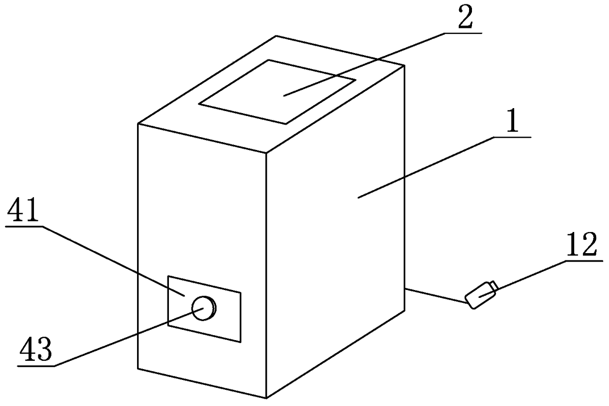
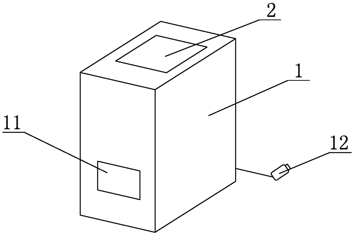
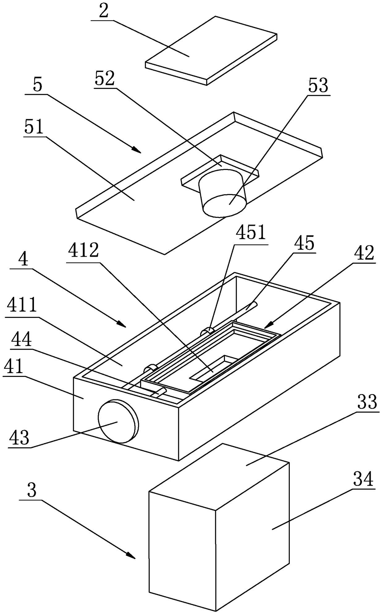
[0025] Embodiment one: if Figure 1 to Figure 5 As shown, a biochip detector includes an outer casing 1 and an image display mechanism 2. The outer casing 1 is provided with a light source mechanism 3, a biochip loading mechanism 4 and an image capture mechanism 5, and the light source mechanism 3 is arranged on the biochip loading mechanism. 4, the image capture mechanism 5 is arranged above the biochip loading mechanism 4, and the image capture mechanism 5 is electrically connected with the image display mechanism 2.
[0026] In this specific embodiment, the light source mechanism 3 includes a light source 31 and a light source circuit board 32. A light source circuit for controlling the strength of the light source 31 is arranged on the light source circuit board 32. The light source 31 is electrically connected to the light source circuit. plate 33. The light source mechanism 3 has a simple structure. A diffuser plate 33 is arranged above the light source 31. The light be...
Embodiment 2
[0036] Embodiment two: if Figure 4 to Figure 6 As shown, a biochip detector includes an outer casing 1 and an image display mechanism 2. The outer casing 1 is provided with a light source mechanism 3, a biochip loading mechanism 4 and an image capture mechanism 5, and the light source mechanism 3 is arranged on the biochip loading mechanism. 4, the image capture mechanism 5 is arranged above the biochip loading mechanism 4, and the image capture mechanism 5 is electrically connected with the image display mechanism 2.
[0037] In this specific embodiment, the light source mechanism 3 includes a light source 31 and a light source circuit board 32. A light source circuit for controlling the strength of the light source 31 is arranged on the light source circuit board 32. The light source 31 is electrically connected to the light source circuit. plate 33. The light source mechanism 3 has a simple structure. A diffuser plate 33 is arranged above the light source 31. The light be...
Embodiment 3
[0047] Embodiment 3: other parts are the same as Embodiment 1 or Embodiment 2, the difference is that there is a gap between the lens 53 and the photosensitive plate 52, and the gap is 1 cm. A gap is set between the lens 53 and the photosensitive plate 52, and the gap can ensure that the imaging circuit can capture a relatively clear image.
PUM
 Abstract
Description
Claims
Application Information
 - R&D
- Intellectual Property
- Life Sciences
- Materials
- Tech Scout
- Unparalleled Data Quality
- Higher Quality Content
- 60% Fewer Hallucinations
Browse by: Latest US Patents, China's latest patents, Technical Efficacy Thesaurus, Application Domain, Technology Topic, Popular Technical Reports.
© 2025 PatSnap. All rights reserved.Legal|Privacy policy|Modern Slavery Act Transparency Statement|Sitemap|About US| Contact US: help@patsnap.com


