A vehicle-mounted wheel set flaw detection method and system

A vehicle-mounted and wheel-set technology, which is applied in the direction of using sound waves/ultrasonic waves/infrasonic waves to analyze solids, etc., can solve the problems of long construction period, low efficiency, and heavy workload of staff, and achieve no need for line construction, simple manual operation, and detection fast and efficient results

Active Publication Date: 2018-08-14
ZHUZHOU CSR TIMES ELECTRIC CO LTD
View PDF10 Cites 14 Cited by
  • Summary
  • Abstract
  • Description
  • Claims
  • Application Information

AI Technical Summary

Problems solved by technology

The disadvantage is that the cost is high, the construction period is long, and the flaw detection area is limited to the shallow layer of the rim, wheel flange and spoke plate. In addition, real-time detection of the health status of the wheel set is impossible
From the above description, we can see that the existing wheel set flaw detection technology has contradictions between flaw detection efficiency and personnel workload and flaw detection coverage and cost, that is, the drop-wheel flaw detection equipment guarantees the flaw detection coverage, and the cost is relatively low, but the efficiency is low , and the workload of the staff is heavy, the efficiency of online flaw detection equipment is higher, but the cost is high, the construction volume is large, and the coverage of flaw detection is limited
Moreover, neither of the above two methods can achieve real-time detection. Therefore, how to solve the contradiction between flaw detection efficiency and personnel workload, flaw detection coverage and cost, and realize wheel set flaw detection while rolling stock is moving has become a key technical problem to be solved urgently.

Method used


Image

  • A vehicle-mounted wheel set flaw detection method and system
  • A vehicle-mounted wheel set flaw detection method and system
  • A vehicle-mounted wheel set flaw detection method and system

Examples


Embodiment Construction

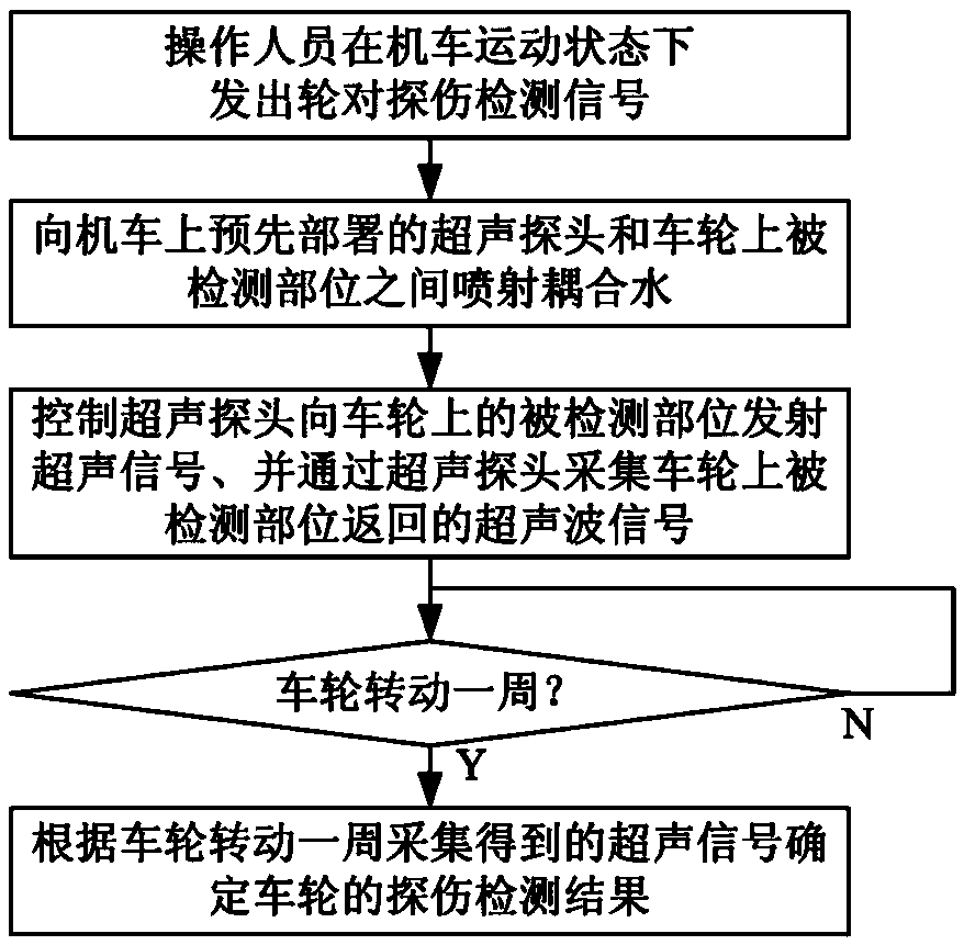
[0037] Such as figure 1 As shown, the steps of the vehicle-mounted wheel set flaw detection method of the present embodiment include:

[0038] 1) The operator sends a wheel set flaw detection signal while the locomotive is in motion;

[0039] 2) After receiving the wheel set flaw detection signal, spray coupling water between the pre-deployed ultrasonic probe on the locomotive and the detected part on the wheel, so that ultrasonic coupling is formed between the ultrasonic probe and the detected part on the wheel, and at the same time control the ultrasonic The probe emits an ultrasonic signal to the detected part on the wheel, and collects the ultrasonic signal returned by the detected part on the wheel through the ultrasonic probe, and determines the flaw detection result of the wheel according to the ultrasonic signal collected by the wheel for one rotation.

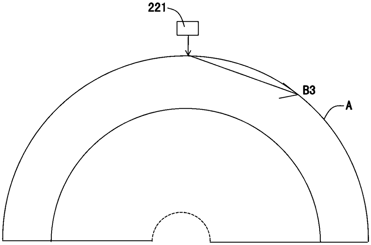
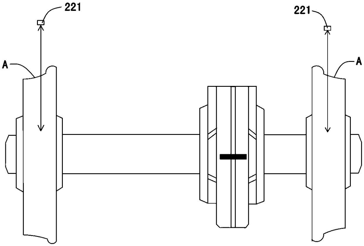
[0040] Such as figure 2 As shown, the vehicle-mounted wheelset flaw detection system of this embodiment includes ...


PUM


Abstract

The invention discloses a vehicle-mounted wheel set flaw detection method and system. The wheel set flaw detection method comprises the steps that coupling water is sprayed between ultrasonic probes pre-installed on a locomotive and detected portions on wheels under control of wheel set flaw detection signals, the ultrasonic probes are controlled to emit ultrasonic signals and collect ultrasonic signals returned by the detected portions on the wheels, and flaw detection results of the wheels are determined according to the ultrasonic signals collected when the wheels revolve one round. The wheel set flaw detection system comprises a cab unit and a bogie unit; the cab unit comprises an ultrasonic detector and a flaw detection controller, the bogie unit comprises a coupling water spraying unit and an ultrasonic probe assembly, and the ultrasonic probe assembly comprises the ultrasonic probes. The vehicle-mounted wheel set flaw detection system can be pre-installed on the locomotive when a locomotive vehicle leaves a factory and has the advantages that detection is fast and efficient, later line construction is not needed, the flaw detection range is wide, all the portions, needing to be detected, of the wheels can be covered, the cost is lower, and the wheel set health state can be detected at any time in the running process of the locomotive.

Description

technical field [0001] The invention relates to a railway wheel set flaw detection technology, in particular to a vehicle-mounted wheel set flaw detection method and system. Background technique [0002] Whether it is high-speed rail or ordinary rail, the speed of trains will be further increased during the "Twelfth Five-Year Plan" period. After the speed of the train is increased, the wheels are restricted by the speed effect and the braking method under the condition of high-speed movement, and their stress state has undergone great changes. Peelability puts forward higher requirements. How to ensure the safety of wheels and axles is one of the important requirements for safe production in the current railway industry. The wheel is the final force-bearing part of the rolling stock. It transmits the load of the rolling stock to the rail and rotates on the rail to complete the operation of the rolling stock. The quality of the wheel performance directly affects the safety...

Claims


Application Information

Patent Timeline
Patent Type & Authority Patents(China)
IPC IPC(8): G01N29/04
Inventor 童磊贺文施蔚加王俊平程浩尤勇
Owner ZHUZHOU CSR TIMES ELECTRIC CO LTD
Why Eureka
Try Eureka