Common voltage adjustment device and method

A common voltage and control device technology, applied in the direction of instruments, static indicators, etc., can solve the problems of manpower, material resources and time, low accuracy of public voltage, inaccurate data records, etc., to achieve accurate debugging, avoid errors, and operate simple effect

Active Publication Date: 2015-12-23
KUSN INFOVISION OPTOELECTRONICS
View PDF8 Cites 9 Cited by
  • Summary
  • Abstract
  • Description
  • Claims
  • Application Information

AI Technical Summary

Problems solved by technology

The above manual debugging method, due to individual differences such as manual experience and proficiency, will inevitably lead to inaccurate data records, resulting in low accuracy of public voltage debugging
Moreover, the number of liquid crystal display devices will be relatively large during the debugging process, and it is necessary to record the common voltage of the liquid crystal display devices for a long time, which consumes a lot of manpower, material resources and time, and the debugging efficiency is very low

Method used


Image

  • Common voltage adjustment device and method
  • Common voltage adjustment device and method
  • Common voltage adjustment device and method

Examples


no. 1 example

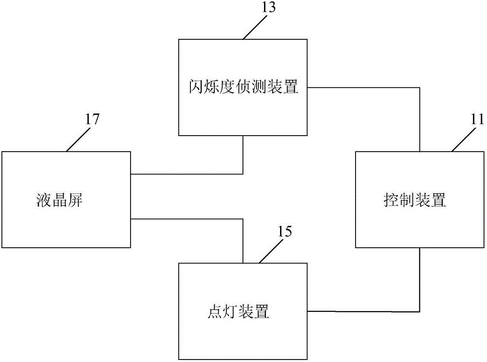
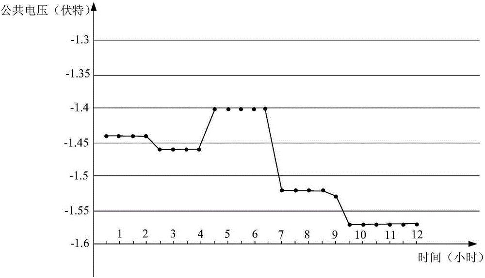
[0025] figure 1 It is a main structural block diagram of the common voltage debugging device provided by the first embodiment of the present invention. figure 2 It is a graph of the relationship between the optimal public voltage and time. Please refer to figure 1 and figure 2 , the public voltage debugging device includes: a control device 11 , a flicker detection device 13 connected to the control device 11 and a lighting device 15 . The flicker detection device 13 and the lighting device 15 are connected with the liquid crystal screen 17 .

[0026] The lighting device 15 is used to control and light the liquid crystal screen 17 according to the test picture provided by the control device 11 and the initial common voltage, so that the liquid crystal screen 17 displays the test picture under the initial common voltage, and the liquid crystal screen 17 lights up under the initial common voltage After a preset period of time, the liquid crystal screen 17 is controlled to ...

no. 2 example

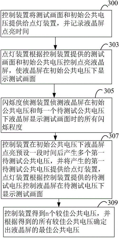
[0044] image 3 It is a flow chart of the steps of the common voltage debugging method provided by the second embodiment of the present invention. Please refer to image 3 , the public voltage debugging method of this embodiment includes the following steps 300-309.

[0045] Step 300, the control device provides the test pattern and the initial public voltage to the lighting device, and records the lighting time of the liquid crystal screen.

[0046] In step 303, the lighting device controls to light the liquid crystal screen according to the test picture provided by the control device and the initial common voltage, so that the liquid crystal screen displays the test picture under the initial common voltage.

[0047] In step 305, the flicker detection device detects all flicker levels of the liquid crystal screen when the liquid crystal screen displays a test picture under the initial common voltage and each common voltage to be tested, and provides all detected flicker lev...

no. 3 example

[0057] Figure 4 It is a flow chart of the steps of the public voltage debugging method provided by the third embodiment of the present invention. Figure 4 is in image 3 improved on the basis of Figure 4 and image 3 The difference is that Figure 4 Step 400 may also be included. Please refer to Figure 4 , the public voltage debugging method of the embodiment of the present invention may also include the following steps 300-309 and 400:

[0058] Wherein steps 300-309 are related to image 3 Same, no more details here.

[0059] Step 400, the initial common voltage is the initial preferred common voltage, then the control device generates a plurality of initial common voltages to be tested after providing the test pattern and the initial common voltage to the lighting device, and generates a plurality of initial common voltages to be tested. The voltage is provided to the lighting device, and the lighting device controls the liquid crystal screen to display the test ...


PUM


Abstract

The invention discloses a common voltage adjustment device and method. The device comprises a control device, and a scintillation detection device and a lighting device which are both in connection with the control device. The lighting device is used for controlling the lighting of a liquid crystal screen according to the test picture provided by the control device and an initial common voltage, and controls the liquid crystal screen to display the test picture under all common voltages to be tested according to all the common voltages to be tested provided by the control device after the liquid crystal screen is lightened for a preset period of time under the initial common voltage; the scintillation detection device is used for detecting all scintillation degrees of the liquid crystal screen when the liquid crystal screen displays the test picture under the initial common voltage and each common voltage to be tested; the control device is used for determining the optimum common voltage of the liquid crystal screen according to all obtained better common voltages. The common voltage adjustment device and method make common voltage adjustment more accurate, have the characteristics of simple operation and lower cost, and improve the common voltage adjustment efficiency.

Description

technical field [0001] The invention relates to the field of display technology, in particular to a common voltage debugging device and method. Background technique [0002] Liquid Crystal Display (LCD) has the advantages of good image quality, small size, light weight, low driving voltage, low power consumption, no radiation and relatively low manufacturing cost, and currently occupies a dominant position in the field of flat panel display. It is widely used in various office automation and audio-visual equipment such as desktop computers, palmtop computers, personal digital assistants (Personal Digital Assistant, PDA), portable phones, and television boxes. [0003] The liquid crystal display device includes an array substrate, a color filter substrate, and a liquid crystal layer sandwiched between the array substrate and the color filter substrate. When the liquid crystal display device is in operation, the driving voltage and the common voltage are respectively applied t...

Claims


Application Information

Patent Timeline
Patent Type & Authority Applications(China)
IPC IPC(8): G09G3/36
Inventor 吴二平闫小能
Owner KUSN INFOVISION OPTOELECTRONICS
Why Eureka
Try Eureka