
A power supply protection circuit

A protection circuit and power supply protection technology, which is applied in the direction of protection reacting to overvoltage, protection reacting to undervoltage or no voltage, etc., can solve the problem of damage to the power supply device 20 of the rear stage, failure to protect the power supply device of the rear stage, and protection of the rear stage power supply device. 20-level power supply equipment is easy to burn, etc., to achieve the effect of expanding the selection range and realizing overvoltage and undervoltage protection.

Active Publication Date: 2019-02-05
KUSN INFOVISION OPTOELECTRONICS
View PDF9 Cites 0 Cited by
  • Summary
  • Abstract
  • Description
  • Claims
  • Application Information

AI Technical Summary

Problems solved by technology

[0004] The power supply chip 10 in the prior art has a built-in overvoltage protection. The overvoltage protection voltage is a constant protection voltage of the power supply chip 10, which can only protect the body of the power supply chip 10 and cannot protect the power supply equipment 20 of the subsequent stage.
When the output voltage signal is higher than the allowable input voltage of the power supply device 20 of the subsequent stage and does not exceed the overvoltage protection voltage of the power supply chip 10, the power supply chip 10 still works normally, and the power supply device 20 of the subsequent stage is easy to burn out under the overvoltage state.
In addition, the current power supply chip 10 does not have undervoltage protection, and when the subsequent power supply equipment 20 works in an undervoltage state for a long time, it is easy to cause damage to the subsequent power supply equipment 20

Method used


Image

  • A power supply protection circuit
  • A power supply protection circuit
  • A power supply protection circuit

Examples


Embodiment 1

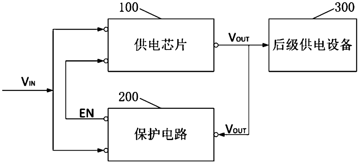
[0048] refer to figure 2 As shown, it is a schematic diagram of a power supply protection circuit provided by Embodiment 1 of the present invention. The technical solution of this embodiment is applicable to the situation where the protection circuit is used to provide power supply protection for different subsequent power supply equipment.

[0049] The power supply protection circuit includes: a power supply chip 100 and a protection circuit 200 .

[0050] The power supply chip 100 includes an input terminal, an output terminal and an enabling control terminal, and the input terminal is used to receive an input voltage signal V IN , the output terminal is used to transmit the output voltage signal V to the subsequent power supply equipment 300 and the protection circuit 200 respectively OUT , the enable control terminal is used to receive the enable signal EN, and the power supply chip 100 works normally or is in a steady state under the control of the enable signal. When...

Embodiment 2

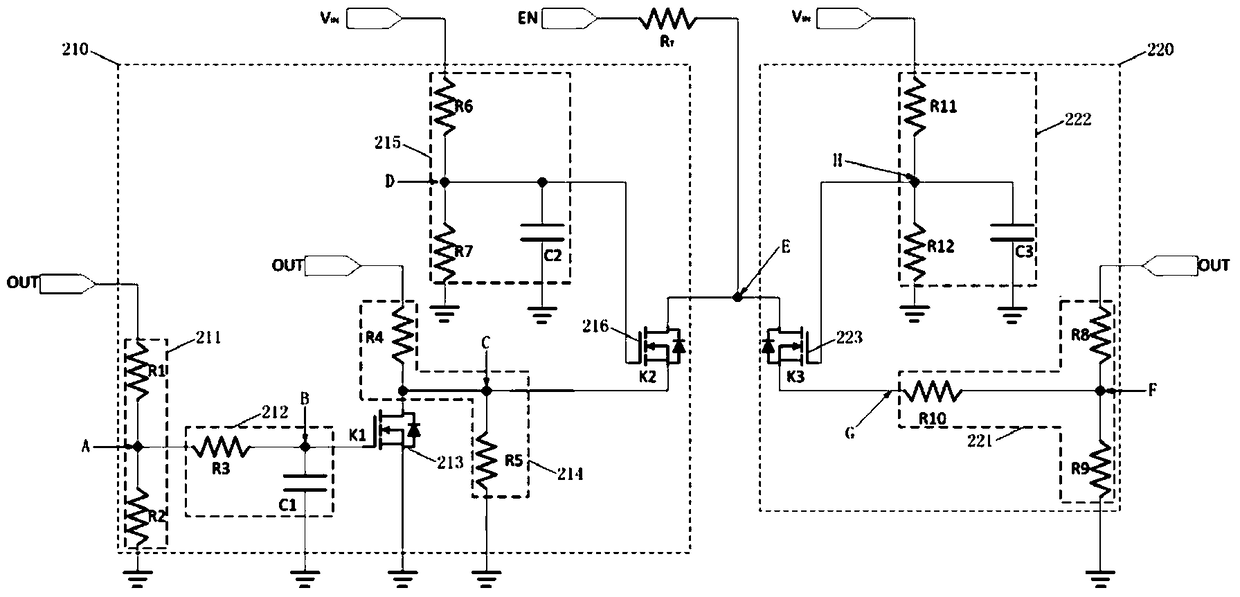
[0062] refer to image 3 As shown, it is a schematic diagram of a protection circuit provided by Embodiment 2 of the present invention. As shown in the figure, the protection circuit 200 is one of the protection circuits of the power supply protection circuit described in the first embodiment above, and the protection circuit 200 includes a clamping resistor R T .

[0063] The overvoltage protection circuit 210 of the protection circuit 200 includes a first input terminal, a second input terminal and an enable output terminal, and the first input terminal of the overvoltage protection circuit 210 is used to receive the input voltage signal V IN , the second input terminal is used to receive the output voltage signal V OUT . The enable output terminal is used to output the enable signal or the enable output terminal is suspended. When the power supply chip 100 is in a steady state, the output terminal of the power supply chip 100 does not output, and the second input terminal...

Embodiment 3

[0097] refer to Figure 4 As shown, it is a schematic diagram of a protection circuit provided by Embodiment 3 of the present invention. As shown in the figure, the protection circuit is one of the power supply protection circuits described in the first embodiment above.

[0098] The protection circuit includes an overvoltage protection circuit 310 and an undervoltage protection circuit 320 . The protection circuit is set to perform overvoltage and undervoltage protection for the subsequent power supply equipment 300 with an operating voltage range of 3.0V˜3.6V.

[0099] The overvoltage protection circuit 310 includes a first resistor R1, a second resistor R2, a third resistor R3, a first capacitor C1, a first switch K1, a fourth resistor R4, a fifth resistor R5, a sixth resistor R6, and a seventh resistor R7 , a second capacitor C2, and a second switch K2.

[0100] Wherein, the first end of the first resistor R1 is connected to the output end of the power supply chip 100, ...


PUM


Abstract

The invention discloses a power supply protection circuit. The power supply protection circuit comprises a power supply chip and a protection circuit, wherein an input end of the power supply chip and a first input end of the protection circuit are respectively used for receiving input voltage signals; an output end of the power supply chip is used for transmitting output voltage signals to a second input end of the protection circuit, and transmitting output voltage signals to post-stage power supply equipment; an enable control end of the power supply chip is connected with an enable output end of the protection circuit, and is used for receiving enable signals output by the protection circuit; when the output voltage signals are within a threshold voltage range preset by the protection circuit, the protection circuit outputs a first enable signal to the power supply chip through the enable output end, and controls the power supply chip to operate normally; and when the output voltage signals exceed the threshold voltage range preset by the protection circuit, the protection circuit outputs a second enable signal to the power supply chip through the enable output end, and controls the power supply chip to be in a steady state. The power supply protection circuit achieves the overvoltage and undervoltage protection of the post-stage power supply equipment through the protection circuit.

Description

technical field [0001] The invention relates to power supply technology, in particular to a power supply protection circuit. Background technique [0002] With the improvement of the precision of electronic products, the electronic products have higher and higher requirements for voltage, and thus higher and higher requirements for power supply (Power). [0003] In the prior art, a power supply chip with internal overvoltage protection is usually selected to perform overvoltage protection for the subsequent power supply equipment. like figure 1 As shown, it is a schematic diagram of a power supply system provided by the prior art. The power supply system includes a power supply chip 10 and a subsequent power supply device 20 , the power supply chip 10 has overvoltage protection, and the power supply chip 10 is preset with an overvoltage protection voltage. Specifically, the output terminal of the power supply chip 10 is connected to the subsequent power supply device 20, ...

Claims


Application Information

Patent Timeline
Patent Type & Authority Patents(China)
IPC IPC(8): H02H3/20H02H3/24
Inventor 刘胜利林沛炀蒋敏
Owner KUSN INFOVISION OPTOELECTRONICS
Learn More