Control handles for catheters

A technology for controlling handles and catheters, applied in catheters and other directions, and can solve problems such as complex designs

Active Publication Date: 2015-12-23
ST JUDE MEDICAL INT HLDG SARL
View PDF10 Cites 42 Cited by
  • Summary
  • Abstract
  • Description
  • Claims
  • Application Information

AI Technical Summary

Problems solved by technology

This can result in a rather complex design involving double sliders or complex wiring within the handle to achieve equal amounts of line being retracted and released

Method used


Image

  • Control handles for catheters
  • Control handles for catheters
  • Control handles for catheters

Examples


Embodiment Construction

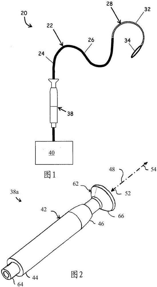
[0048] see figure 1 , a catheter system 20 is shown in the disclosed embodiment. Catheter system 20 includes an elongated catheter assembly 22 having a proximal portion 24 , an intermediate portion 26 , and a distal portion 28 . Distal portion 28 of catheter assembly 22 includes a steering section 32 and may also include an end effector 34 . Catheter system 20 may be equipped with instrumentation for determining at least one operational state of catheter assembly 22 . Examples of operating parameters that may enable predictive operating conditions include force, temperature, time interval (eg, duration or delay), and / or flow rate (eg, irrigation flow rate). In some embodiments, the instrumentation is disposed within end effector 34 .

[0049] The steering section 32 also includes one or more pull wires 36 (shown in the various figures) disposed within the elongate catheter assembly 22 and attached to the distal end of the steering section 32, wherein the at least one pull ...


PUM


Abstract

A plunger-type control handle comprising an elongate housing (42) for controlling the deflection of a distal tip of a catheter. The control handle includes a spool (112) driven by a gear (102), the spool being connected to the proximal end of at least one pull wire (32a). For bi-directional deflection, a second proximal end (32b) of a pull wire is connected to the spool such that when one of the proximal ends is collected by the spool, the other of the proximal ends is released in an equal amount. The gear is operatively coupled to the plunger (92) and engages a gear rack (84) disposed on the control handle housing, such that when there is relative movement between the housing and the plunger, the gear and spool are rotated.

Description

[0001] related application [0002] This application claims U.S. Patent Application No. 13 / 930,988, filed June 28, 2013, U.S. Provisional Patent Application No. 61 / 819,335, filed May 3, 2013, and U.S. Provisional Patent Application No. 61 / 819,335, filed April 30, 2013 Benefit of Application No. 61 / 817,661. technical field [0003] The present invention relates generally to handles for catheters, and more particularly to control handles for manipulating the distal ends of catheters. Background technique [0004] Control handles for deflecting the distal end of the catheter come in various configurations. One form of control handle is the so-called "piston-type" handle, which includes a generally cylindrical housing with a piston extending therefrom. The operator typically holds the housing in the palm of the hand with four fingers and uses the thumb to move the piston forward and backward relative to the housing along the actuation axis. The pull wire or pull wires are co...

Claims


Application Information

Patent Timeline
Patent Type & Authority Applications(China)
IPC IPC(8): A61M25/01
CPCA61M25/0136A61M25/0147A61M25/0133
Inventor A·L·罗莫什努
Owner ST JUDE MEDICAL INT HLDG SARL
Why Eureka
Try Eureka