Method for producing motor vehicle door locks with a rolling surface as a locking part contour

A technology for locking components, motor vehicles, applied in the direction of lock applications, building locks, vehicle locks, etc.

Active Publication Date: 2015-12-23
KIEKERT AG
View PDF6 Cites 1 Cited by
  • Summary
  • Abstract
  • Description
  • Claims
  • Application Information

AI Technical Summary

Problems solved by technology

This disadvantageous noise cannot be completely avoided even with punched flutes running obliquely relative to one another according to DE 10 2007 060 626 A1

Method used


Image

  • Method for producing motor vehicle door locks with a rolling surface as a locking part contour
  • Method for producing motor vehicle door locks with a rolling surface as a locking part contour
  • Method for producing motor vehicle door locks with a rolling surface as a locking part contour

Examples


Embodiment Construction

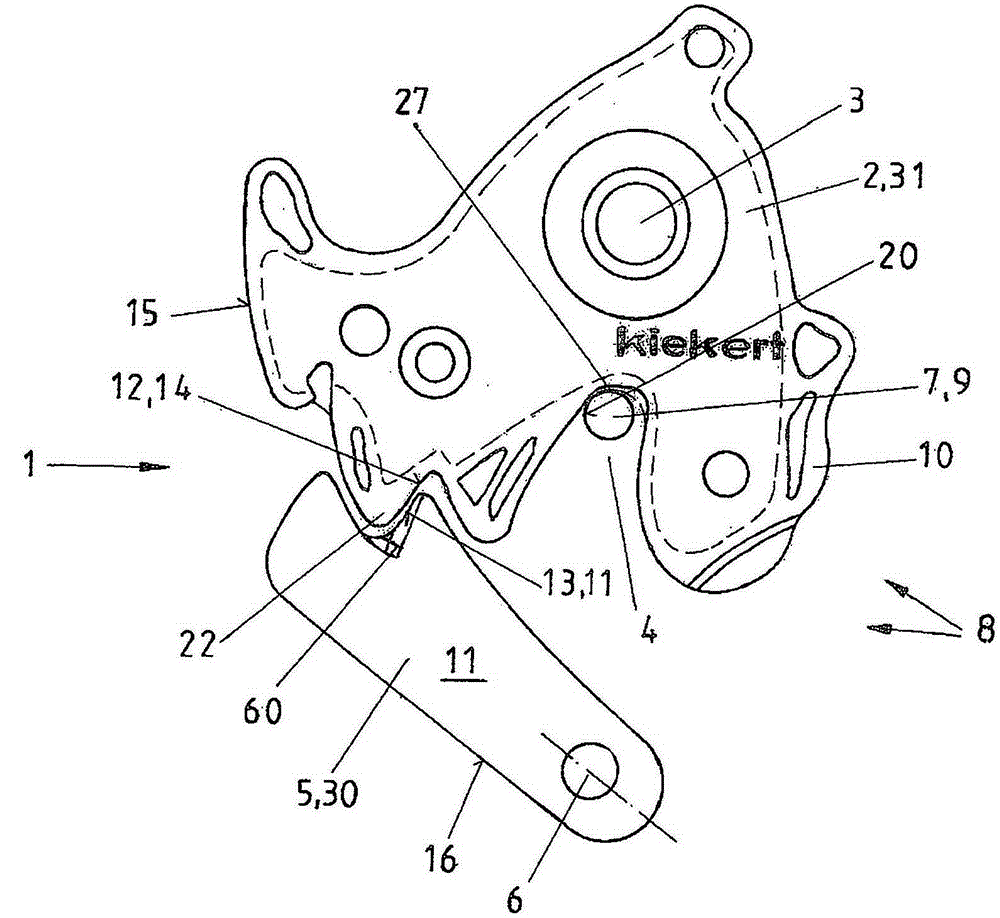
[0023] figure 1 A top view of a motor vehicle lock 1 is shown, in which a rotary locking fork 2 movable about an axis 3 surrounds a locking bow leg 9 of a locking bow (or lock catch) 7 . That is to say, the locked state of the motor vehicle lock 1 is reflected here, wherein the rotary locking fork 2 is fixed by the pawl 5 which can pivot around the pawl axis 6, that is to say, the motor vehicle lock 1 is only locked when the pawl 5 has been pivoted away ( This is achieved by the motor vehicle door handle (not shown here) and can only be opened again. The locking bow leg 9 moves on the rotary locking fork 2 via the receptacle 4 as far as the depth bottom 27 and thus ensures the locked state of the motor vehicle door, also not shown here, wherein the locking parts 30 , 31 ie the locking pawl 5 and the rotary The locking fork 2 is part of the motor vehicle door, while the locking bow 7 with the locking bow legs 9 is fastened to the body of the motor vehicle. The locking parts 3...


PUM


Abstract

The invention relates to a method for producing motor vehicle door locks with the locking parts: a rotary latch and a pawl. Said latch and the pawl are stamped from rolled sheet metal defining vertical or approximately vertical edges with corresponding latch surfaces on the rotary latch and the pawl, and subsequently are provided with a covering whilst maintaining the catch surfaces. After stamping, the locking parts are bent in the region of the main latch and/or another latch resulting in the formation a contour which is void of stamped channels, and are then inserted into the lock housing box.

Description

technical field [0001] The invention relates to a method for the manufacture of a motor vehicle lock with locking parts, namely a locking pawl and a swivel yoke, in which method the swivel yoke and the locking pawl are punched out of rolled sheet material to give a vertical Or approximately vertical edge (or called side), said edge has the corresponding locking surface on the rotary locking fork and the locking pawl, and then gives the rotary locking fork and The locking claws are equipped with casings. The invention also relates to a motor vehicle lock with a rotary locking fork and a pawl which locks the rotary locking fork in the locked state, wherein the rotary locking fork and the locking pawl are on the free end of the locking part on the edge produced when the locking part is stamped There is a corresponding locking surface at the top and a cladding vacating the locking surface. Background technique [0002] It is known in principle that the creaking noises that occ...

Claims


Application Information

Patent Timeline
Patent Type & Authority Applications(China)
IPC IPC(8): E05B85/26E05B77/40E05B77/36
CPCB21D53/38E05B77/36E05B77/40E05B85/26B21D5/00B21D22/02E05B79/10E05B85/22
Inventor T·班德尔W·波利T·瓦尔德曼
Owner KIEKERT AG
Why Eureka
Try Eureka