Stirling cycle machine

An engine, external combustion technology, used in mechanical equipment, engine components, engine seals, etc., can solve problems such as increasing engine noise, increasing piston wear, and bulky machinery.

Active Publication Date: 2015-12-23
NEW POWER CONCEPTS
View PDF22 Cites 11 Cited by
  • Summary
  • Abstract
  • Description
  • Claims
  • Application Information

AI Technical Summary

Problems solved by technology

Common problems encountered with this type of machinery are: friction created by the sliding piston due to misalignment of the piston within the cylinder, and lateral forces on the piston due to its coupling to the rotating crankshaft
These increased side loads increase engine noise, increase piston wear and reduce engine ef

Method used


Image

  • Stirling cycle machine
  • Stirling cycle machine
  • Stirling cycle machine

Examples


Embodiment Construction

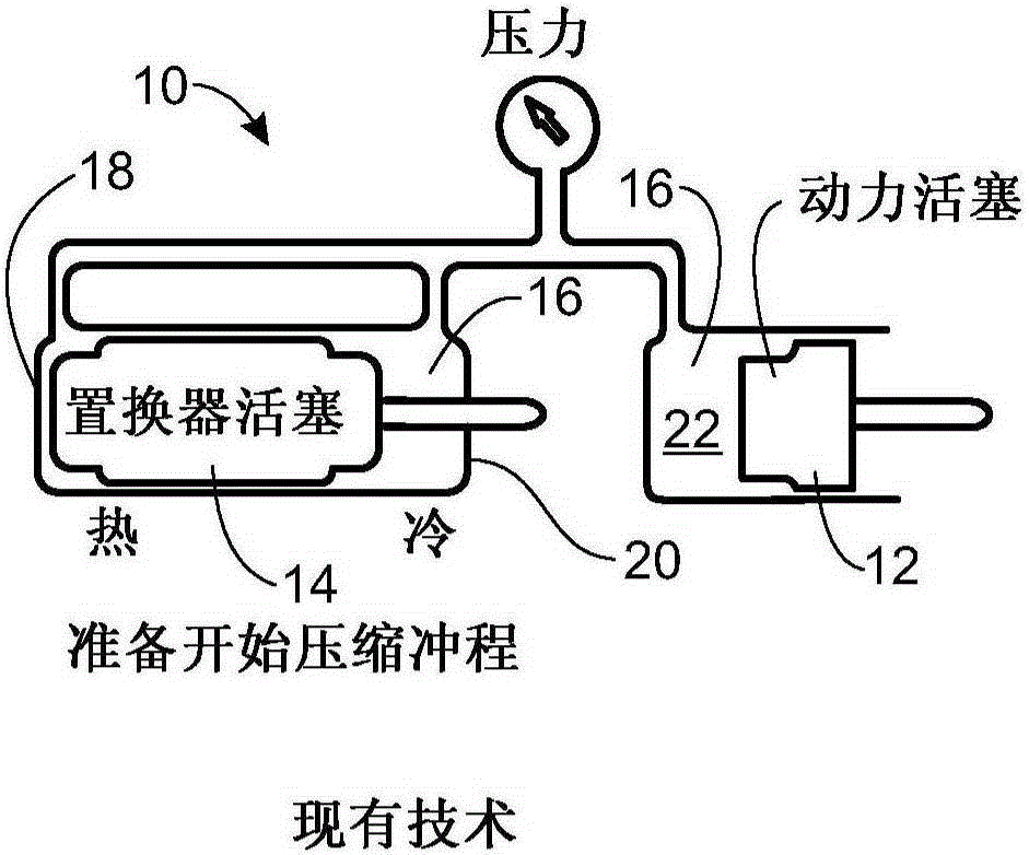
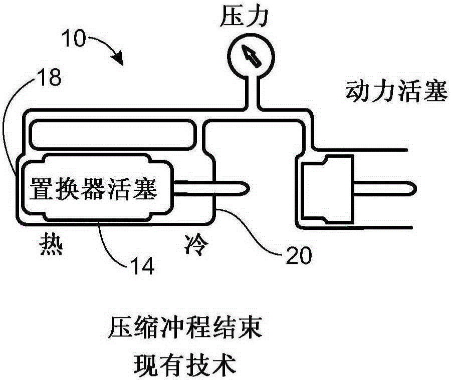
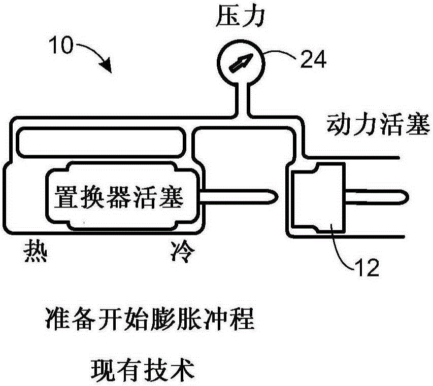
[0116] Stirling cycle machines, including engines and refrigerators, have a long technical heritage and are described in detail in Walker's Stirling Engines, Oxford University Press (1980) Stirling cycle machine, the contents of which are hereby incorporated by reference. The principle of a Stirling cycle engine is the mechanical realization of the Stirling thermodynamic cycle: constant-volume heating of the gas in the cylinder, isothermal expansion of the gas (during which work is done by driving the piston), constant-volume cooling and isothermal compression. Additional background related to various aspects of the Stirling cycle machine and its improvements are discussed in "The Phillips Stirling Engine" by Hargreaves (Elsevier, Amsterdam, 1991), which is also incorporated herein by reference way incorporated into this article.

[0117] refer to Figures 1A-1EThe operating principle of the Stirling cycle machine can be easily described, wherein the same reference numerals a...


PUM


Abstract

An external combustion engine. The external combustion engine includes a working fluid and includes a burner element for heating the working fluid of the engine, at least one heater head defining a working space containing the working fluid, at least one piston cylinder containing a piston for compressing the working fluid, a cooler for cooling the working fluid, a crankcase including a crankshaft for producing an engine output, a rocking beam rotating about a rocker pivot for driving the crankshaft, a piston rod connected to the piston, a rocking beam driven by the piston rod, and a connecting rod connected at a first end to the rocking beam and at a second end to a crankshaft to convert rotary motion of the rocking beam to rotary motion of the crankshaft. Also, the external combustion engine including a piston rod seal unit including a housing, a cylinder gland, and at least one floating rod seal assembly mounted in the cylinder gland, the floating rod seal assembly comprising at least one rod seal mounted onto the floating rod seal assembly.

Description

technical field [0001] The present invention relates to a machine, and more particularly, to a Stirling cycle machine and components thereof. Background technique [0002] Many machines, such as internal combustion engines, external combustion engines, compressors, and other reciprocating machines, employ arrangements of pistons and drive mechanisms to convert the linear motion of the reciprocating pistons into rotary motion. In most applications, the piston is housed in the cylinder. Common problems encountered with such machines are: friction created by the sliding piston due to misalignment of the piston within the cylinder, and lateral forces exerted on the piston due to its coupling to the rotating crankshaft. These increased side loads increase engine noise, increase piston wear and reduce engine efficiency and life. Furthermore, due to side loads, the drive mechanism requires more power to overcome these frictional forces, thus reducing the efficiency of the machine...

Claims


Application Information

Patent Timeline
IPC IPC(8): F02G1/053
CPCF02G1/0535F02G2253/03F02G2253/80
Inventor 克里斯托佛·C·朗根费尔德普拉桑特·巴特
Owner NEW POWER CONCEPTS
Why Eureka
Try Eureka