
Automatic clamping device applied to automatic sponge cutting mechanism

An automatic cutting and clamping device technology, which is applied in metal processing and other directions, can solve the problems of no device capable of cutting circles, lower production efficiency, and low accuracy of manual cutting circles, so as to achieve convenient cutting and good results

Active Publication Date: 2015-12-30
苏州由派克包装材料有限公司
View PDF7 Cites 20 Cited by
  • Summary
  • Abstract
  • Description
  • Claims
  • Application Information

AI Technical Summary

Problems solved by technology

[0002] At present, when making warm earmuffs, the interior needs to be filled with sponge, and the sponge needs to be cut into small circular shapes. The existing method is to cut it with manual scissors, which is very troublesome and greatly reduces production efficiency. The precision of the cut circle is low;
[0003] And the existing sponge is cut into blocks and adopts resistance wire cutting, and its cutting precision is higher, but it does not have the device that can cut circles

Method used


Image

  • Automatic clamping device applied to automatic sponge cutting mechanism
  • Automatic clamping device applied to automatic sponge cutting mechanism

Examples


Embodiment Construction

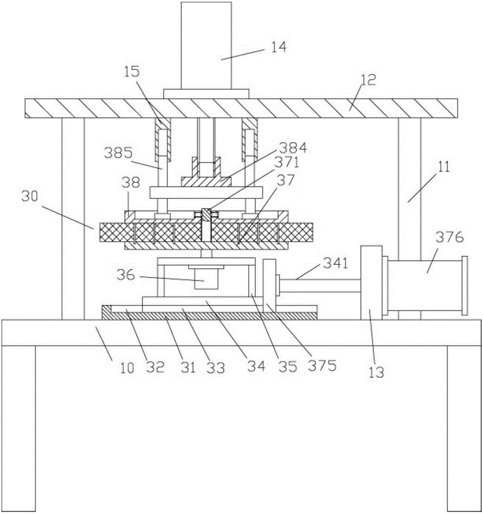
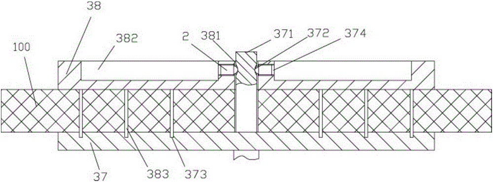
[0015] Examples, see e.g. Figure 1 to Figure 2 As shown, an automatic clamping device for a sponge automatic cutting mechanism includes a frame 10, a sliding track 31 and a pillar 11 are fixed on the top surface of the frame 10, and the top of the pillar 11 is fixed on the upper top plate 12, and the upper The upper platen pressing motor 14 is fixed on the top plate 12, and the output shaft of the upper platen pressing motor 14 passes through the upper top plate 12 and is screwed on the screwed column 384 provided on the top of the upper platen 38. The top surface of the upper platen 38 is fixed with a plurality of stop rods 385, and the stop rods 385 are inserted into a plurality of sleeves 15 provided on the bottom surface of the upper top plate 12. The top surface of the sliding track 31 has a chute 32, and the slide block 33 is inserted in the chute 32, the top surface of the slider 33 is fixed with a moving plate 34, the moving plate 34 is fixed with a support frame 35, ...


PUM


Abstract

The invention discloses an automatic clamping device applied to an automatic sponge cutting mechanism. The automatic clamping device applied to the automatic sponge cutting mechanism comprises a rack, wherein a sliding rail and a support pillar are fixed on the top surface of the rack; the top of the support pillar is fixed on an upper top plate; an upper pressing disk lower pressing motor is fixed on the upper top plate; output shafts of the upper pressing disk lower pressing motor penetrate downwards through the upper top plate and are screwed onto a screwing pillar arranged at the top of an upper pressing disk; a plurality of limiting rods are fixed on the top surface of the upper pressing disk; the limiting rods are inserted and sheathed in a plurality of sleeves on the bottom surface of the upper top plate; a sliding slot is formed in the top surface of the sliding rail; a sliding block is inserted and sheathed in the sliding slot; a movable plate is fixed on the top surface of the sliding block; a support frame is fixed on the movable plate; a driving motor is fixed at the bottom surface of a top plate of the support frame; an output shaft of the driving motor stretches out of the top plate of the support frame and is fixedly provided with a bottom plate; an insertion rod extending upwards is arranged at the middle part of the top surface of the bottom plate. The automatic clamping device applied to the automatic sponge cutting mechanism can be mounted at the position of a resistance wire cutting device, and is capable of automatically fixing the upper pressing disk on the insertion rod, fixing sponge blocks and automatically cutting the sponge blocks; the effect is excellent.

Description

Technical field: [0001] The invention relates to the technical field of sponge cutting, in particular to an automatic clamping device for a sponge automatic cutting mechanism. Background technique: [0002] At present, when making warm earmuffs, the interior needs to be filled with sponge, and the sponge needs to be cut into small circular shapes. The existing method is to use manual scissors to cut it off, which is very troublesome and greatly reduces production efficiency. The precision of the cut circle is low; [0003] And existing sponge is cut into what block shape adopts to have resistance wire cutting, and its cutting precision is higher, but it does not have the device that can cut circle. Invention content: [0004] The purpose of the present invention is to overcome the deficiencies of the prior art and provide an automatic clamping device for a sponge automatic cutting mechanism, which can be installed at the resistance wire cutting device, and can automatical...

Claims


Application Information

Patent Timeline
IPC IPC(8): B26D7/02B26F3/12
Inventor 王胤华尤吉吴春慧周小春傅野吴崧浩
Owner 苏州由派克包装材料有限公司
Features
  • Generate Ideas
  • Intellectual Property
  • Life Sciences
  • Materials
  • Tech Scout
  • Unparalleled Data Quality
  • Higher Quality Content
  • 60% Fewer Hallucinations
Learn More