Multi-connecting-rod anti-collision mechanism and intelligent moving body

An anti-collision mechanism and multi-link technology, applied in transportation and packaging, vehicle safety arrangements, bumpers, etc., can solve the problems of vehicle body obstacle damage, collision obstacles, and failure to identify collisions, and achieve the effect of avoiding damage

Active Publication Date: 2015-12-30
HANGZHOU JIAZHI TECH CO LTD
View PDF8 Cites 13 Cited by
  • Summary
  • Abstract
  • Description
  • Claims
  • Application Information

AI Technical Summary

Problems solved by technology

[0002] The intelligent moving body that moves autonomously will encounter obstacles during the travel process. The general solution is to install multiple touch sensors on the intelligent moving body, and distribute them from multiple angles on the part of the body with a high collision probability, because the sensor When the price is high and the distribution of sensors is scarce, the area between two adjacent sensors may become a collision blind spot, which cannot effectively identify the collision situation. Therefore, the existing technology has the disadvantages of high cost and failure to identify collisions. Under the situation that all distance sensors fail, the moving body itself will collide with the obstacle. If it is not stopped in time, it may cause damage to the vehicle body itself and the obstacle. Therefore, the purpose of the present invention is to reduce costs and improve the degree of collision recognition

Method used


Image

  • Multi-connecting-rod anti-collision mechanism and intelligent moving body
  • Multi-connecting-rod anti-collision mechanism and intelligent moving body
  • Multi-connecting-rod anti-collision mechanism and intelligent moving body

Examples


Embodiment Construction

[0024] The present invention will be described in further detail below in conjunction with the accompanying drawings and specific embodiments.

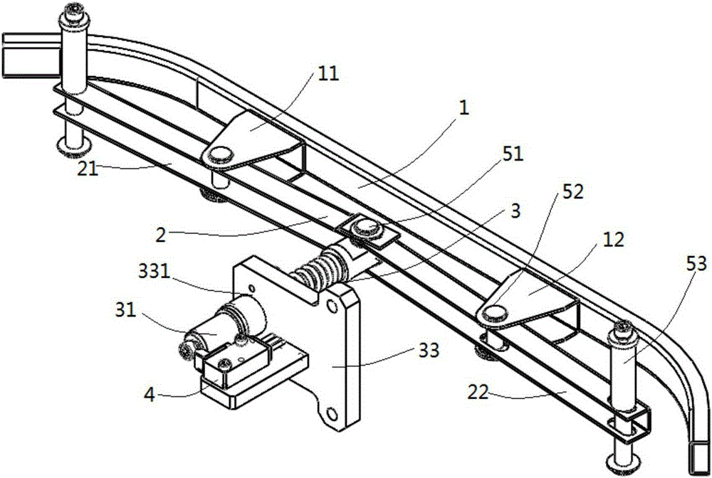
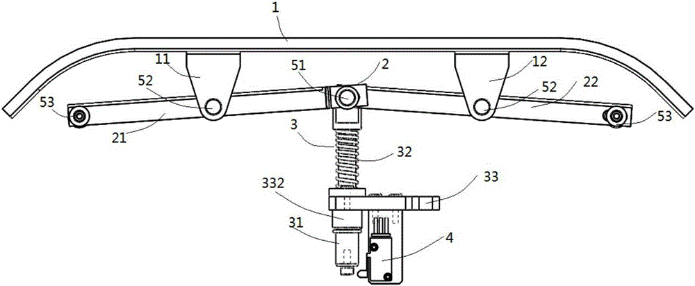
[0025] Such as figure 1 , 2 As shown, the multi-link anti-collision mechanism for intelligent moving bodies in the present invention includes a collision bar 1, a link mechanism 2, a telescopic mechanism 3, a touch sensor 4 and connecting parts. The connecting part includes a first pin 51 , two second pins 52 and two third pins 53 .

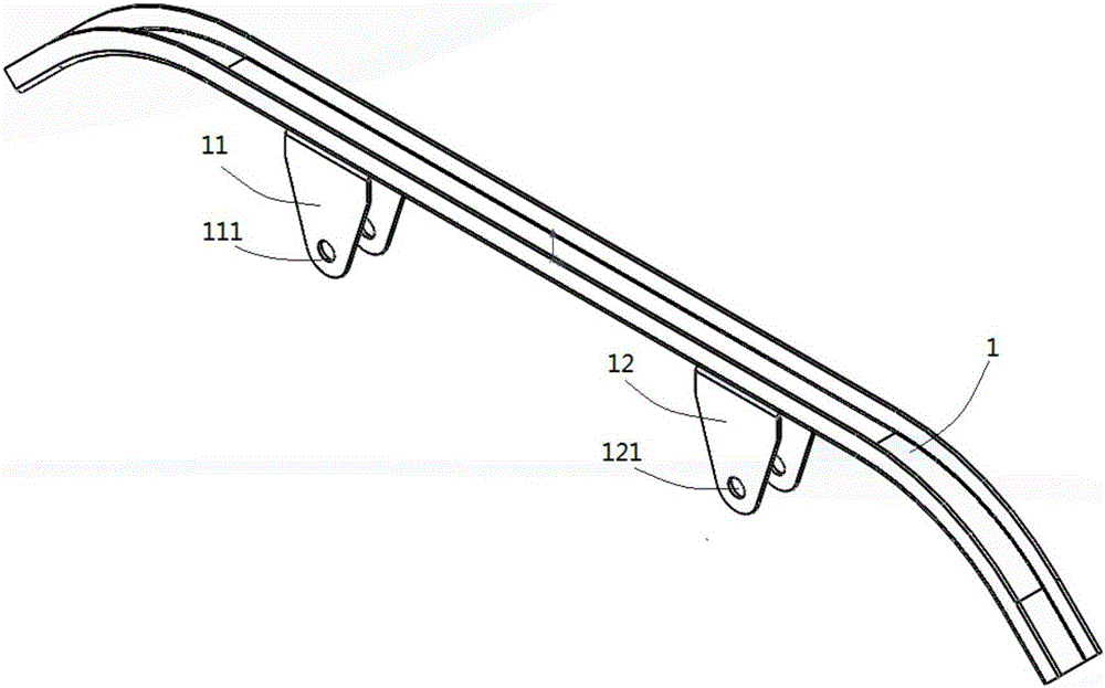
[0026] Such as figure 2 , 3 As shown, the collision bar 1 is a long elastic metal sheet. In this embodiment, the cross section is U-shaped, and its shape can be adjusted according to actual needs. The left and right sides of the collision bar 1 are respectively fixed by welding or screws. Support foot 11, U-shaped right support foot 12, the two sides of left support foot 11 all have the first through hole 111, the two sides of right support foot 12 all have the second through hole 121, the two throu...


PUM


Abstract

The invention discloses a multi-connecting-rod anti-collision mechanism and an intelligent moving body. The anti-collision mechanism comprises a collision rod, a connecting rod mechanism and a telescopic mechanism, wherein the connecting rod mechanism comprises a first supporting rod and a second supporting rod, the first supporting rod is in rotating connection with the intelligent moving body and the collision rod and is in rotating and sliding connection with the telescopic mechanism, and the second supporting rod is in rotating and sliding connection with the intelligent moving body and the collision rod and is in rotating connection with the telescopic mechanism; the telescopic mechanism comprises a spring and moves in the compressing direction of the spring. According to the anti-collision mechanism, connecting rods can rotate and slide relatively, and the connecting rods and a vehicle body can rotate and slide relatively; when the anti-collision mechanism collides with an object by different angles and at different positions, the connecting rod mechanism and the telescopic mechanism are pushed to move backwards, a buffering effect is realized, a collision signal can be generated when the tail of the telescopic mechanism makes contact with a touch sensor, the intelligent moving body can give an instruction, such as stopping power output, according to the collision signal, and then further damage is avoided.

Description

technical field [0001] The invention relates to an anti-collision mechanism, in particular to a multi-link anti-collision mechanism and an intelligent moving body. Background technique [0002] The intelligent moving body that moves autonomously will encounter obstacles during the travel process. The general solution is to install and use multiple touch sensors on the intelligent moving body, and distribute them from multiple angles on the part of the body with a high collision probability, because the sensor When the price is high and the distribution of sensors is scarce, the area between two adjacent sensors may become a collision blind spot, which cannot effectively identify the collision situation. Therefore, the existing technology has the disadvantages of high cost and failure to identify collisions. In the case where all the distance sensors fail, the moving body itself will collide with the obstacle. If the vehicle is not stopped in time, it may cause damage to the ...

Claims


Application Information

Patent Timeline
Patent Type & Authority Applications(China)
IPC IPC(8): B60R19/18B60R21/0136
CPCB60R19/18B60R21/0136B60R2019/186
Inventor 张学垠
Owner HANGZHOU JIAZHI TECH CO LTD
Why Eureka
Try Eureka