Floating slab limiting device and floating track bed

A technology of a limit device and a floating plate, which is applied in the field of rail transit, can solve the problems of hard collision, reduce the effect of vibration reduction, and pull out upward, so as to reduce hard collision and friction, avoid the effect of vibration reduction, and avoid pulling upward out effect

Inactive Publication Date: 2019-08-20
BEIJING JIUZHOUYIGUI SHOCK & VIBRATION ISOLATION
View PDF0 Cites 0 Cited by
  • Summary
  • Abstract
  • Description
  • Claims
  • Application Information

AI Technical Summary

Problems solved by technology

However, for the steel spring floating slab, the simple horizontal limiter of the base of the vibration isolator can meet the working conditions such as underground lines, but it cannot meet the requirements for the steel spring floating slab on the bridge, especially in the curved section. Setting concrete limit stops will greatly increase driving safety
In addition, when the concrete limit stop is installed, it often causes a hard collision between the floating slab and the concrete limit stop, thus reducing the vibration reduction effect and increasing safety hazards. The ups and downs of the floating plate will cause the cushion pad to be driven upward, which may cause irreversible upward pull-out after long-term use; again, the current floating plate limit device has a short service life and is not easy to replace

Method used


Image

  • Floating slab limiting device and floating track bed
  • Floating slab limiting device and floating track bed
  • Floating slab limiting device and floating track bed

Examples


Embodiment Construction

[0023] The specific implementation manners of the present disclosure will be further described in detail below with reference to the drawings and embodiments. The following examples are used to illustrate the present disclosure, but not to limit the scope of the present disclosure.

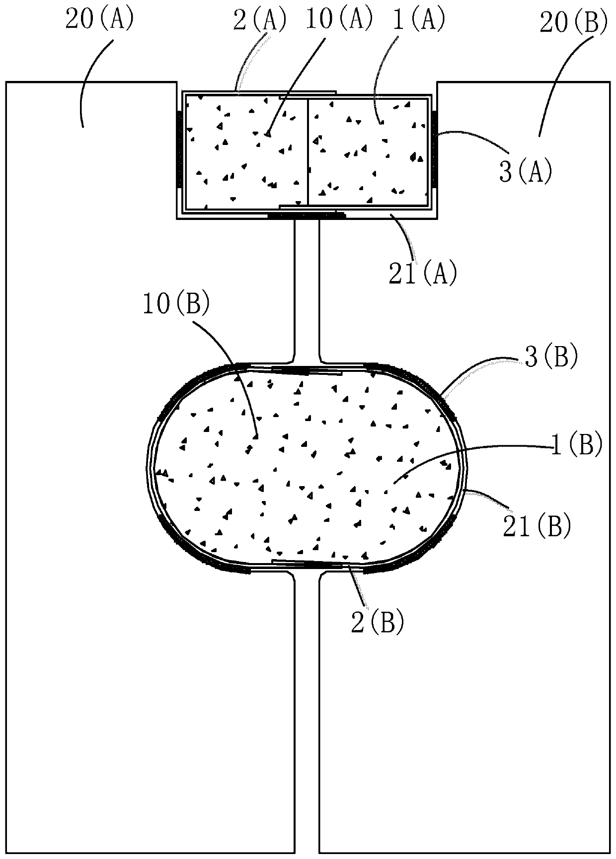
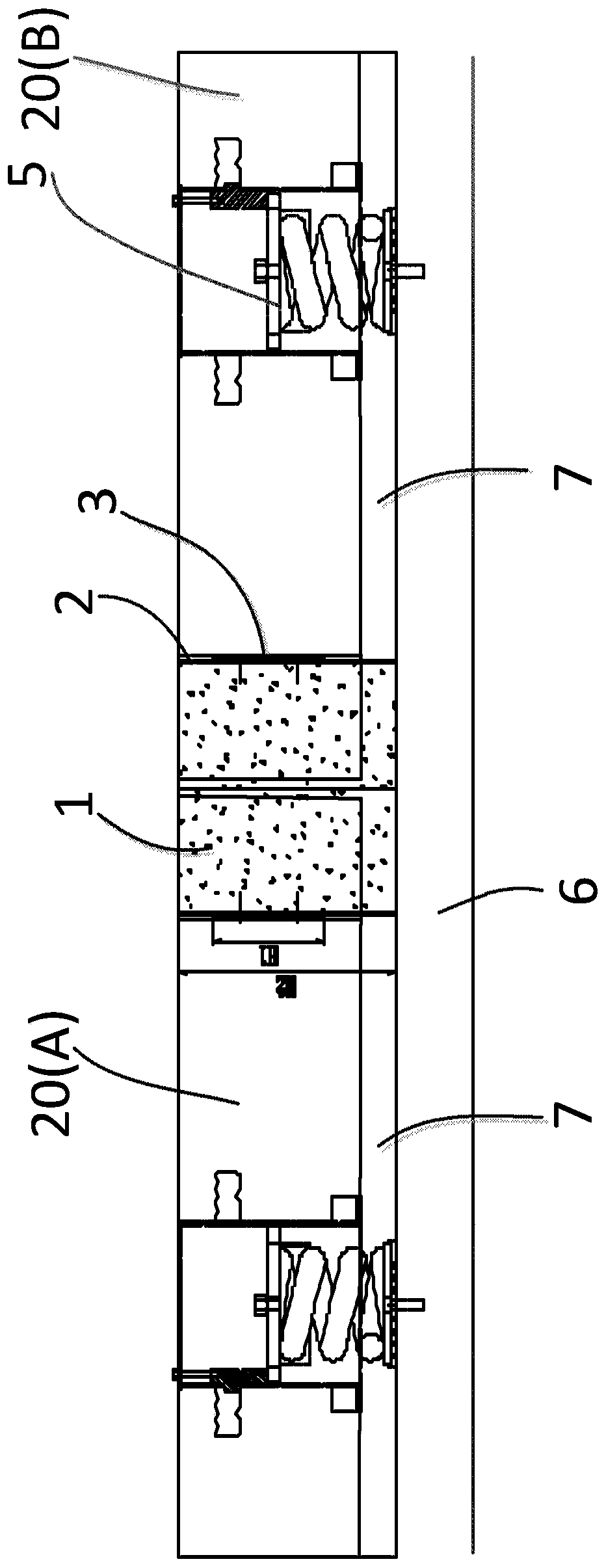
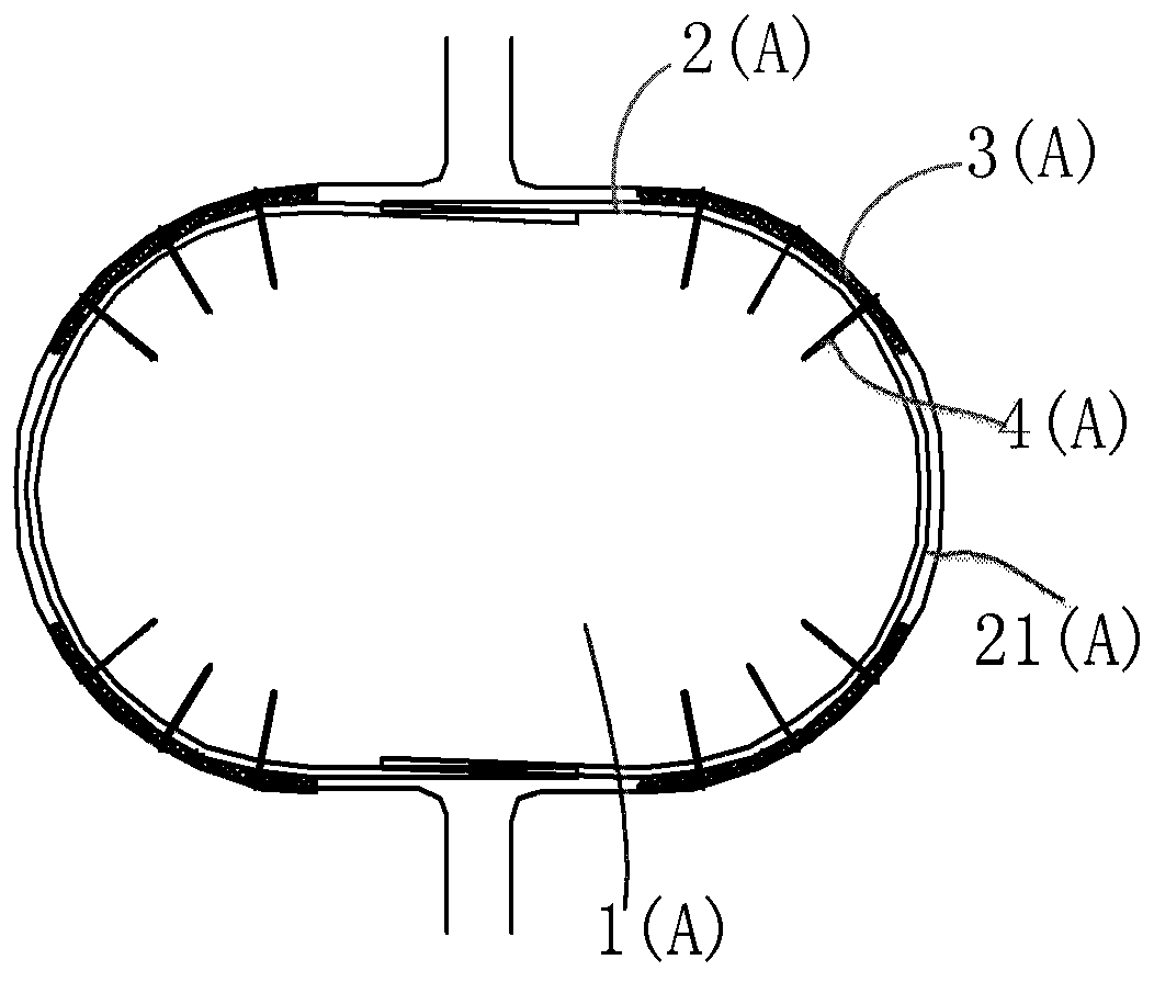
[0024] figure 1 A preferred embodiment of a floating plate limiting device according to the present disclosure is shown. As shown in the figure, the floating slab limiting device 10 includes a concrete limiting block arranged in the notch 21 of the floating slab 20 , and the shape of the concrete limiting stopper is substantially the same as that of the notch 21 . Between the concrete limit block and the floating plate 20, there is a buffer pad assembly which is anchored to the concrete limit block. The rigid plate 8 (such as Figure 4 shown), wherein, the material of the cushion body 3 can be rubber or other polymer materials, and its technical indicators should meet the relevant design requir...


PUM


Abstract

The invention relates to the technical field of rail transit and discloses a floating slab limiting device and a floating track bed. The floating slab limiting device comprises a concrete limiting stopping block arranged in a gap of a floating slab; a buffering pad component connected with the concrete limiting stopping block in an anchored manner is arranged between the concrete limiting stoppingblock and the floating slab; the buffering pad component comprises a buffering pad main body and a rigid plate which is arranged between the buffering pad main body and the floating slab; and the rigid plate is in smooth contact with the floating slab. According to the floating slab limiting device and the floating track bed, as the buffering pad component connected with the concrete limiting stopping block in an anchored manner is arranged between the concrete limiting stopping block and the floating slab, the buffering pad component comprises the buffering pad main body and the rigid platewhich is arranged between the buffering pad main body and the floating slab, and the rigid plate is in smooth contact with the floating slab, irreversible upward pull-out phenomenon of the buffering pad component is avoided.

Description

technical field [0001] The present disclosure relates to the technical field of rail transit, and in particular to a floating slab limiting device and a floating ballast bed including the floating slab limiting device. Background technique [0002] In the ballast bed, the floating plate limit device is usually used to realize the limit requirement of the ballast bed. For example, the traditional steel spring floating plate usually uses a horizontal limiter at the base of the vibration isolator or a side (middle) limit stop to achieve the limit function. In other types of floating plates (such as rubber pad floating plates, etc.) Concrete limit stops have also been used in ordinary track beds. However, for the steel spring floating slab, the simple horizontal limiter of the base of the vibration isolator can meet the working conditions such as underground lines, but it cannot meet the requirements for the steel spring floating slab on the bridge, especially in the curved sec...

Claims


Application Information

Patent Timeline
Patent Type & Authority Applications(China)
IPC IPC(8): E01B1/00E01B19/00
CPCE01B1/00E01B19/003
Inventor 梁国君邵斌丁德云任奇李腾周迎春
Owner BEIJING JIUZHOUYIGUI SHOCK & VIBRATION ISOLATION
Why Eureka
Try Eureka