
Vertical bow and front edge drainage combined damping structure used for low speed full formed ship

A vertical bow and hypertrophy technology, which is applied in the field of combined drag reduction structure of vertical bow and leading edge drainage, can solve the problems of vortex generation, increase of frictional resistance of the whole ship, delay, etc., to reduce total resistance and reduce wave-making resistance. , the effect of reducing the viscous pressure resistance

Active Publication Date: 2015-12-30
SHANGHAI JIAO TONG UNIV
View PDF5 Cites 4 Cited by
  • Summary
  • Abstract
  • Description
  • Claims
  • Application Information

AI Technical Summary

Problems solved by technology

Although the drainage through openings changes the flow field distribution in the bow and stern areas of the ship, delays the transition from laminar flow to turbulent flow, and reduces the frictional resistance at the stern, the total frictional resistance of the whole ship is still increased.
In addition, if the shape of the groove is not smooth enough during the application process, vortices will be generated due to the rapid change of fluid pressure, and additional shape resistance will be generated inside the groove
[0005] The application of bulbous bow technology has indeed achieved the effect of drag reduction and energy saving, but the bulbous bow technology can be clearly reflected on ships with a large bow angle, and the effect on ships with a small bow angle needs to be improved
In addition, because the current information about the bulbous bow is all for a specific ship type, some bulbous bows that are considered to be very successful may not be able to obtain satisfactory results when applied to other ships, so in the process of further research It is necessary to discuss the drag reduction effect of bulbous bows by distinguishing different ship types

Method used


Image

  • Vertical bow and front edge drainage combined damping structure used for low speed full formed ship
  • Vertical bow and front edge drainage combined damping structure used for low speed full formed ship
  • Vertical bow and front edge drainage combined damping structure used for low speed full formed ship

Examples


Embodiment Construction

[0030] In order to make the technical means, creative features, goals and effects achieved by the present invention easy to understand, the present invention will be further described below in conjunction with specific embodiments.

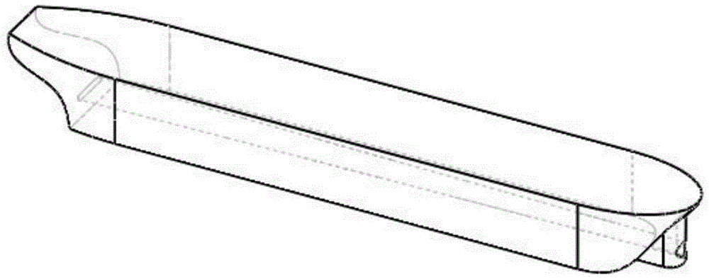
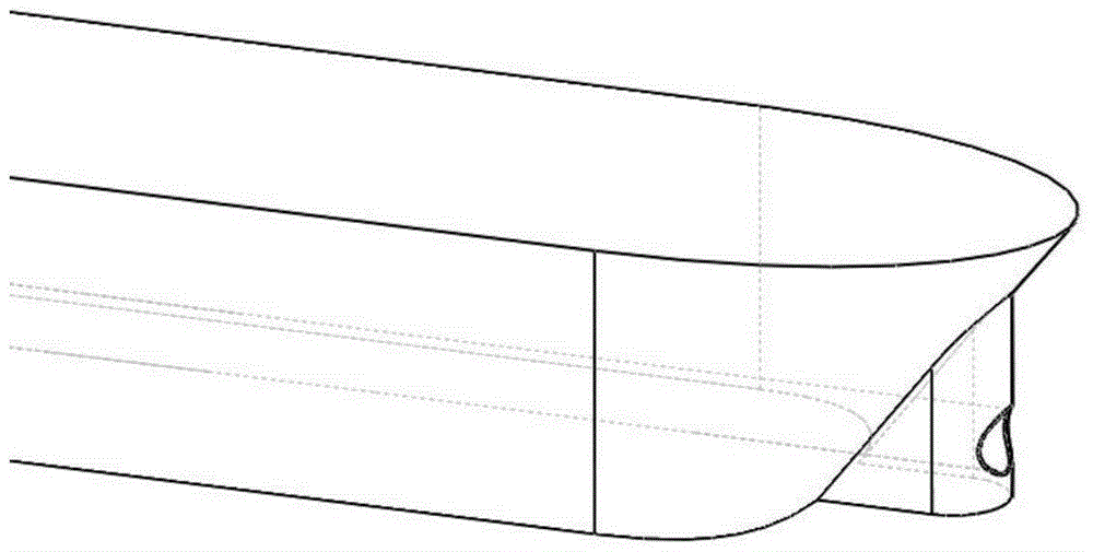
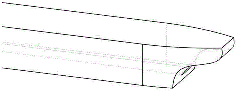
[0031] see figure 1 , figure 2 and image 3 , the invention discloses a combined drag reduction structure of vertical bow and leading edge drainage for low-speed fat and large ships, including a hull, a vertical bow is installed at the bow position of the hull, and a circular bow is opened at the front end of the vertical bow A rectangular hole with rounded corners is opened at the stern of the hull, the circular hole and the rectangular hole with rounded corners are connected back and forth, and a smooth transition is formed inside the hull to form a flow channel for the fluid to pass through, and the parameters of the structure The determination can be made according to a specific method.

[0032] In the first part, the outstanding advantage...


PUM


Abstract

The invention discloses a vertical bow and front edge drainage combined damping structure used for a low speed full formed ship of which the ship speed is lower than 12 knots and a block coefficient (CB) is larger than 0.8. The structure comprises a ship body, a vertical bow is arranged at the head position of the ship body, the front end of the vertical bow is provided with a round hole, a rounded rectangle hole is formed in the tail of the ship body, the round hole and the rounded rectangle hole are communicated from front to back and are in smooth transition in the ship body to form a runner through which fluid passes. The invention innovatively puts forwards a concept of the vertical bow instead of a bulbous bow; further, a vertical bow technology and a front edge drainage technology are combined to effectively reduce wave-making resistance, and further reduce viscosity pressure resistance in a greater degree, and total resistance of the whole ship is reduced by more than 3%.

Description

technical field [0001] The present invention relates to the field of hull drag reduction structures, in particular, particularly to a structure with a square coefficient C for a speed of less than 12 knots. B The vertical bow and leading edge drainage combined drag reduction structure of the low-speed fat ship greater than 0.8. Background technique [0002] The bulbous bow is mainly used to reduce the wave-making resistance caused by the loss of energy due to the generation of waves during the ship's driving. The principle is to cause favorable wave system interference. Reasonable setting of the bulbous bow can make the wave-making of the bulbous bow form a favorable interference with the bow shear wave of the main hull, that is, let the trough of the wave-making of the bulbous bow and the crest of the bow wave be at the same position, so that the synthesized bow wave is significantly decrease. [0003] The leading edge drainage technology mainly reduces the viscous press...

Claims


Application Information

Patent Timeline
IPC IPC(8): B63B1/06B63B1/32
CPCY02T70/10
Inventor 万德成张笑通姚昊陈芝燚齐英鹤杨昆
Owner SHANGHAI JIAO TONG UNIV
Learn More