Working method of fast-tumbling target racemic cell sails for on-orbit servicing
A working method and cell technology, which can be applied to tools, space navigation equipment, transportation and packaging, etc., can solve the problems of secondary damage to the uncontrolled satellite body, low racemization efficiency, low racemization cost, etc., so as to shorten the racemization time, Effects of reduced complexity and reduced power requirements
- Summary
- Abstract
- Description
- Claims
- Application Information
AI Technical Summary
Problems solved by technology
Method used
Image
Examples
specific Embodiment approach 1
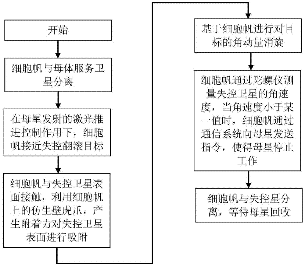
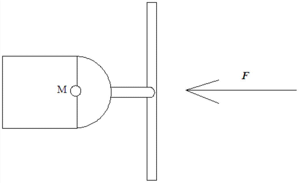
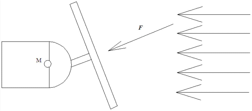
[0028] Specific embodiment one: combine 1 to Figure 5Describe this embodiment, the working method of the on-orbit service-oriented rapid rolling target derotation cell sail in this embodiment. The derotation is completed by the cooperation of the parent star and the cell sail. The parent star is the carrier of the laser and is the energy source of the derotation torque. At the same time, as the sending end of the control command, it is the control center of the cell sail, and the cell sail, as the angular momentum derotation device attached to the out-of-control satellite, is the specific executive mechanism for performing the derotation task.
specific Embodiment approach 2
[0029] Specific implementation mode two: combination Figure 1 to Figure 5 Describe this embodiment, the described working method of this embodiment comprises the following steps:
[0030] Step 1, the cell sail is separated from the parent service satellite;
[0031] Step 2. Under the action of the laser propulsion control emitted by the parent star, the cell sail approaches the uncontrolled rolling target;
[0032] Step 3, the cell sail is in contact with the surface of the out-of-control satellite, and the bionic gecko claw on the cell sail is used to generate adhesion to the surface of the out-of-control satellite;
[0033] Step 4. Perform angular momentum racemization on the target based on the cell sail;
[0034] Step 5. The cell sail measures the angular velocity of the out-of-control satellite through the gyroscope. When the angular velocity is less than the preset 10 - 3 When the threshold of rad / s is reached, the cell sail sends instructions to the mother star thr...
specific Embodiment approach 3
[0036] Specific implementation mode three: combination Figure 1 to Figure 5 To illustrate this embodiment, laser propulsion control is adopted in step 2 of this embodiment. The specific principle is: the surface of the cell sail is made of photonic graphene material, and based on the principle that photonic graphene emits electrons outward under light irradiation, the parent star passes through Launch the laser and align it with the graphene light sail structure on the cell sail. The photonic graphene material absorbs energy and ejects electrons outward under the laser irradiation, generating a reactionary thrust. The thrust is changed by changing the intensity of the laser or changing the irradiation of the light sail. The area is controlled, and the direction of the thrust is controlled by changing the position of the light sail surface. Other compositions and connections are the same as those in the second embodiment.
PUM
 Abstract
Description
Claims
Application Information
 - R&D
- Intellectual Property
- Life Sciences
- Materials
- Tech Scout
- Unparalleled Data Quality
- Higher Quality Content
- 60% Fewer Hallucinations
Browse by: Latest US Patents, China's latest patents, Technical Efficacy Thesaurus, Application Domain, Technology Topic, Popular Technical Reports.
© 2025 PatSnap. All rights reserved.Legal|Privacy policy|Modern Slavery Act Transparency Statement|Sitemap|About US| Contact US: help@patsnap.com


