A high-sensitivity resonant system based on straight waveguide-feedback waveguide-ring-straight waveguide

A high-sensitivity, resonant system technology, applied in the optical field, can solve the problems of insufficient measurement accuracy of fiber resonators, and achieve the effects of reducing the required space, high sensitivity, and improving stability

Active Publication Date: 2017-08-25
HARBIN INST OF TECH
View PDF7 Cites 0 Cited by
  • Summary
  • Abstract
  • Description
  • Claims
  • Application Information

AI Technical Summary

Problems solved by technology

[0003] The purpose of the present invention is to solve the problem of insufficient measurement accuracy of the existing fiber resonator, and propose a high-sensitivity resonant system based on straight waveguide-feedback waveguide-ring-straight waveguide

Method used


Image

  • A high-sensitivity resonant system based on straight waveguide-feedback waveguide-ring-straight waveguide

Examples


specific Embodiment approach 1

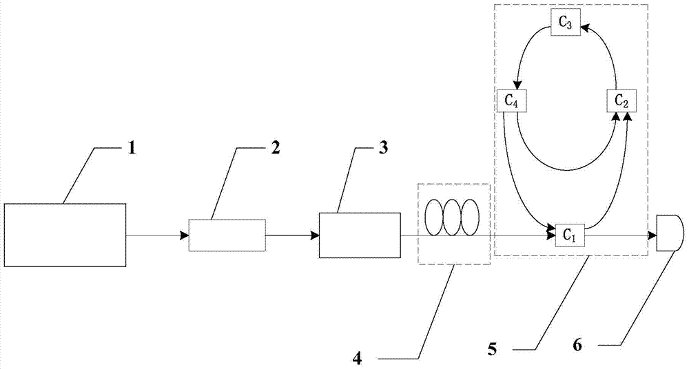
[0016] Specific implementation mode one: combine figure 1 Describe this embodiment, a high-sensitivity resonant system based on straight waveguide-feedback waveguide-ring-straight waveguide described in this embodiment, which includes a laser 1, an attenuator 2, an isolator 3, a polarization controller 4, and a resonant structure 5 and a detector 6, the transmitting end of the laser 1 is connected to the input end of the attenuator 2, the output end of the attenuator 2 is connected to the input end of the isolator 3, and the output end of the isolator 3 is connected to the input end of the resonant structure 5, A polarization controller 4 is arranged on the optical fiber between the output end of the isolator 3 and the input end of the resonant structure 5, and the output end of the resonant structure 5 is connected to the receiving end of the detector 6;

[0017] The resonant structure 5 includes a first coupler C 1 , the second coupler C 2 , the third coupler C 3 and the ...

specific Embodiment approach 2

[0020] Specific implementation mode two: combination figure 1Describe this embodiment. This embodiment is a further limitation of a high-sensitivity resonant system based on straight waveguide-feedback waveguide-ring-straight waveguide described in Embodiment 1. All optical fibers are SMF-28 single-mode optical fibers .

specific Embodiment approach 3

[0021] Specific implementation mode three: combination figure 1 Describe this embodiment. This embodiment is a further definition of a high-sensitivity resonant system based on straight waveguide-feedback waveguide-ring-straight waveguide described in Embodiment 1. The optical fiber in the ring resonator and feedback waveguide The overall length ratio is L 反 / L 环 = 1.6 or L 反 / L 环 =1.4,L 反 is the total length of the fiber in the feedback waveguide, L 环 is the total length of the fiber in the ring resonator.


PUM


Abstract

The invention provides a straight waveguide, feedback waveguide and circle-straight waveguide high-sensitivity resonance system, belongs to the field of optics, and solves the problem that the conventional optical fiber resonant cavity is poor in measuring accuracy. Compared with the conventional single-ring resonant cavity structure, the system provided by the invention has the advantages that a second coupler C2 and a fourth coupler C4 are additionally introduced; through setting of coupling coefficients of a first coupler C1, the second coupler C2, a third coupler C3 and the fourth coupler C4, a certain ratio of the length of optical fibers in a ring-shaped resonant cavity to that of optical fibers in feedback waveguide is ensured, so that a Fano linear spectral line can be output, and the high-sensitivity spectral line can improve the measuring accuracy of the optical fiber resonant cavity. The system is mainly applied to high-precision measurement.

Description

technical field [0001] The invention relates to a high-sensitivity resonant system based on straight waveguide-feedback waveguide-ring-straight waveguide, which belongs to the field of optics. Background technique [0002] Resonant cavities are widely used in metrology, optical sensing, quantum information processing, and biomedical engineering. Due to the advantages of small size, light weight, simple structure, low power consumption, and easy connection to computers, fiber resonant cavities are used in temperature measurement. , Refractive index, velocity, acceleration sound field, electric field, pressure and strain, etc. are widely used, and in the fields of biology, chemistry and environmental monitoring, under the conditions of high voltage and strong electromagnetic interference, or in small and closed spaces, optical fiber Resonant cavities have extraordinary monitoring and measurement capabilities. The spectral lines output by the existing fiber resonators are conc...

Claims


Application Information

Patent Timeline
Patent Type & Authority Patents(China)
IPC IPC(8): G01D5/26
Inventor 掌蕴东于长秋吴泳锋李慧袁萍
Owner HARBIN INST OF TECH
Why Eureka
Try Eureka