Rotary wafer de-waxing equipment

A rotary wafer technology, applied in electrical components, semiconductor/solid-state device manufacturing, circuits, etc., can solve the problems that the wafer surface wax cannot be completely removed, the wafer is unevenly heated, and affects normal use, etc., to improve the wax removal effect, Uniform heating and improved heating efficiency

Inactive Publication Date: 2015-12-30
TIANJIN XINTUO ELECTRONICS SCI & TECH
View PDF0 Cites 0 Cited by
  • Summary
  • Abstract
  • Description
  • Claims
  • Application Information

AI Technical Summary

Problems solved by technology

[0002] When removing wax on the surface of the wafer, the method of heating to remove wax is prone to uneven heating of the wafer, resulting in a significantly better wax removal effect on the heated surface than the non-heated surface, so that the wax on the surface of the wafer cannot be completely removed, affecting its normal use

Method used


Image

  • Rotary wafer de-waxing equipment

Examples


Embodiment 1

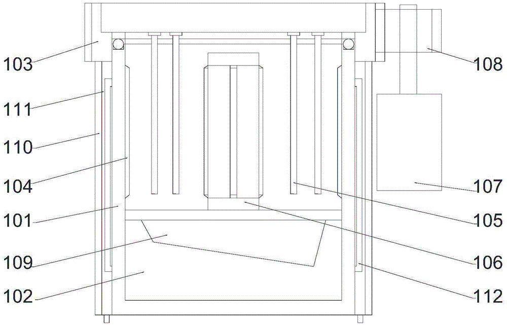
[0028] In order to achieve the effect of driving the movable end cover to rotate, in this embodiment, preferably, the driving device includes a driving motor 107 and a transmission gear 108 arranged on the output shaft of the driving motor 107, and the transmission gear 108 is connected to the The teeth on the movable end cap 103 are meshed.

[0029] In order to reduce the friction between the movable end cover and the upper end surface of the heating chamber, in this embodiment, preferably, balls are provided on the upper end surface of the heating chamber 101, and the rotating end cover 103 is opposed to the The heating bin 101 rotates horizontally.

[0030] In order to avoid heat loss, in this embodiment, preferably, an insulation layer 110 is provided outside the heating chamber 101, and a temperature control cavity 111 is formed between the outer wall of the heating chamber 101 and the insulation layer 110. .

[0031] In order to facilitate timely cooling of the heating...


PUM


Abstract

The invention discloses a rotary wafer de-waxing equipment. The rotary wafer de-waxing equipment sequentially comprises a wax storage chamber, a heating bin and a rotary end cover from up to down, wherein an inner wall of the heating bin is provided with an electric heater, the middle portion of the mobile end cover is provided with a sliding block for clamping a wafer, the inner wall of the heating bin is further provided with a temperature sensor, an outer wall of the mobile end cover is provided with teeth, an outer side of the heating bin is provided with a driving device used for driving the mobile end cover to rotate relative to the heating bin, the middle portion of the mobile end cover is provided with a hole sinking, the upper end of the sliding block is clamped in the hole sinking, the lower end of the sliding block is arranged at an inner side of the heating bin, and the middle portion of the heating bin is provided with a cylinder structure. According to the rotary wafer de-waxing equipment, the end cover structure capable of relatively rotating is employed, the sliding block in a circumferential arrangement mode is employed, the middle portion and the side wall are equipped with heating equipment, and heating de-waxing for the middle portion and the side wall is realized.

Description

technical field [0001] The invention relates to a rotary wafer wax removal equipment. Background technique [0002] When the wafer surface is dewaxed, heating the wafer is likely to cause uneven heating of the wafer, resulting in a significantly better dewaxing effect on the heated surface than the non-heated surface, so that the wax on the wafer surface cannot be completely removed, affecting its normal use. Contents of the invention [0003] The object of the present invention is to provide a rotary wafer wax removal equipment, which can improve the problems existing in the prior art. By adopting a relatively rotatable end cover structure and a ring-arranged slider structure, at the same time, the middle and side Heating equipment is installed on the wall to realize simultaneous heating and wax removal in the middle and side. [0004] The present invention is realized through the following technical solutions: [0005] A rotary wafer wax removal equipment, which includ...

Claims


Application Information

Patent Timeline
Patent Type & Authority Applications(China)
IPC IPC(8): H01L21/67
CPCH01L21/67115
Inventor 张明
Owner TIANJIN XINTUO ELECTRONICS SCI & TECH
Why Eureka
Try Eureka