electrical connector

A technology for electrical connectors and contact parts, applied in the direction of contact parts, etc., can solve the problems of easy bending deformation or displacement, insufficient strength, and reduce costs, and achieve the effects of reducing processes, improving manufacturing capacity, and reducing costs.

Active Publication Date: 2018-12-18
SHANGHAI TIANCHENG COMM TECH
View PDF6 Cites 0 Cited by
  • Summary
  • Abstract
  • Description
  • Claims
  • Application Information

AI Technical Summary

Problems solved by technology

However, the single conductive terminal is generally slender and thin, and its strength is not enough. It is easy to be bent, deformed or shifted during installation and positioning, and it is troublesome to manufacture, which is not conducive to reducing costs.

Method used


Image

  • electrical connector
  • electrical connector
  • electrical connector

Examples


Embodiment Construction

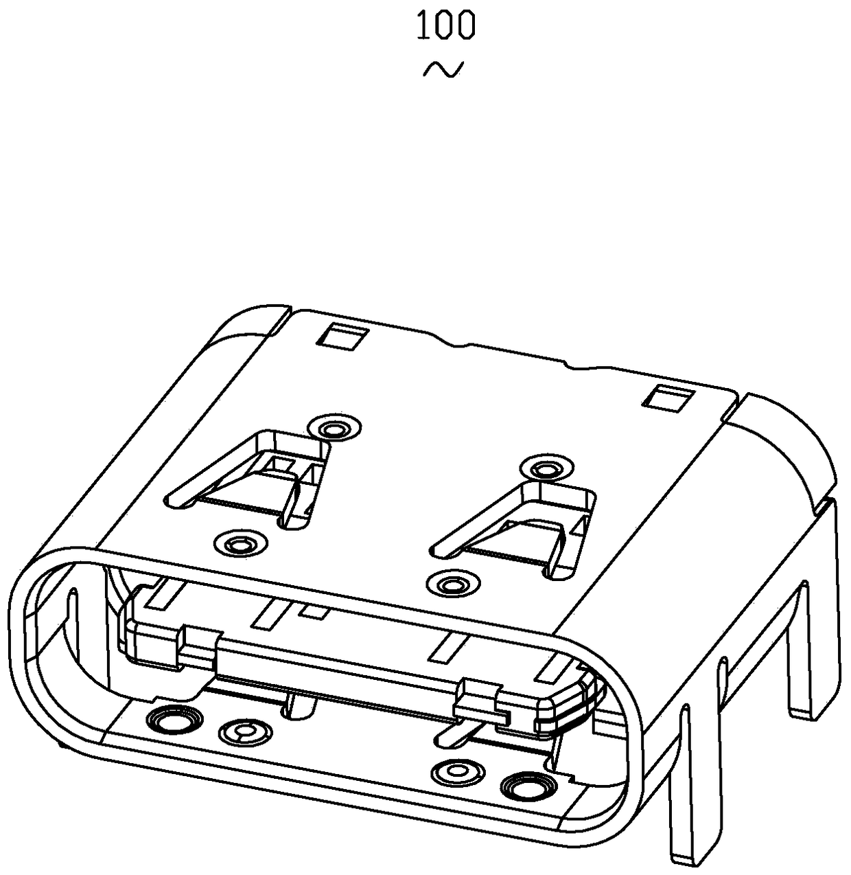
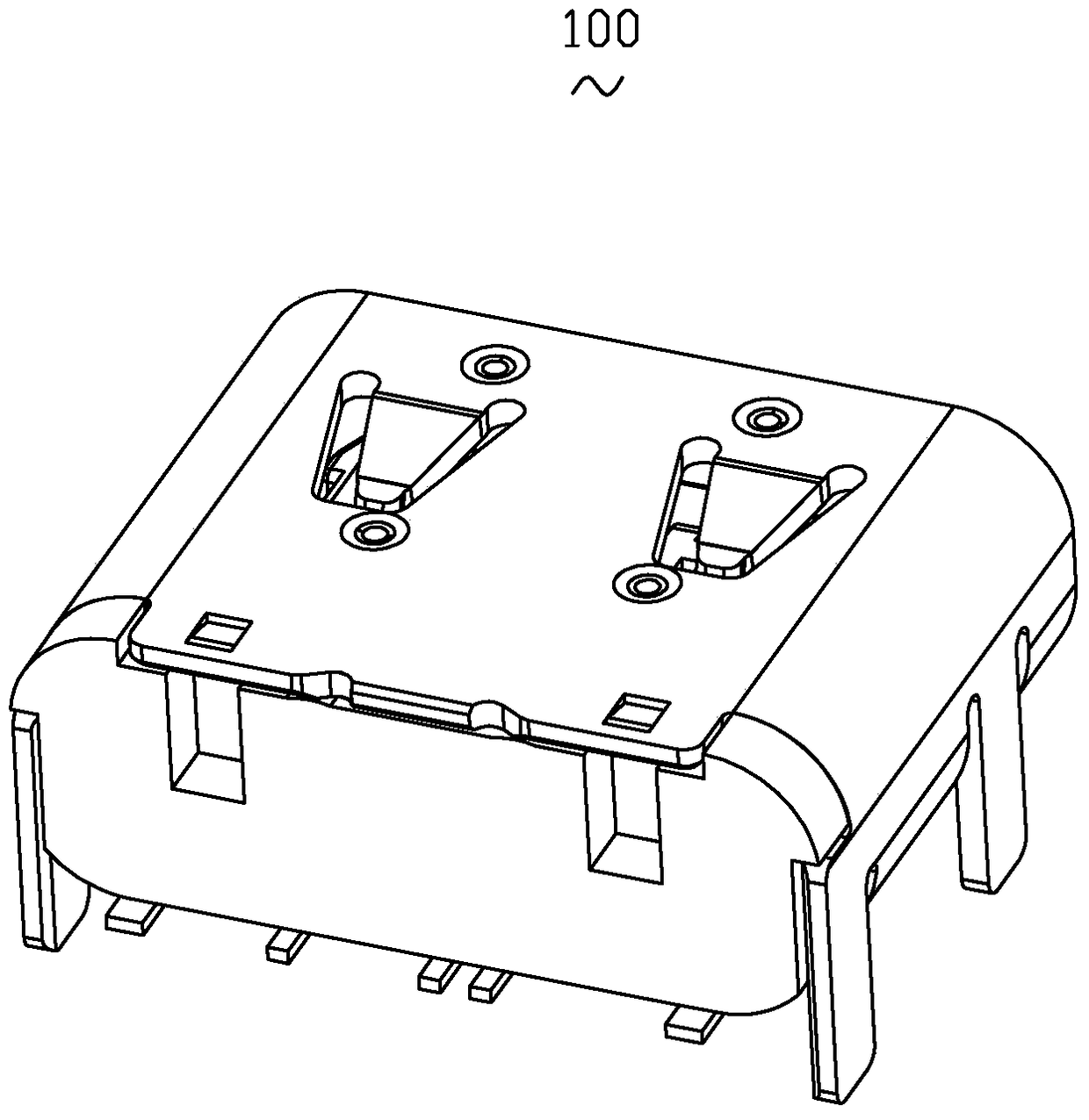
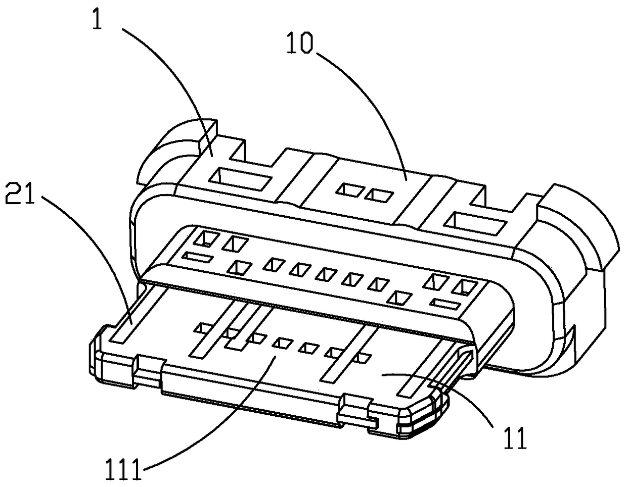
[0052] Please refer to Figures 1 to 7 As shown, it is the electrical connector 100 of the first embodiment of the present invention, the electrical connector 100 is a USB2.0 electrical connector 100 suitable for the interface frame of USB3.1 Type-C, that is, it does not include two pairs High-speed differential signal terminal (not shown). In other implementation manners, the electrical connector 100 may also be a standard USB3.1 Type-C connector including the two pairs of high-speed differential signal terminals.

[0053]In this embodiment, the electrical connector 100 includes an insulating body 1 and a conductive terminal group 2 installed on the insulating body 1. The insulating body 1 includes a base 10 and a tongue 11 extending forward from the base 10. The tongue plate 11 is provided with an upper surface 111 and a lower surface 112, the conductive terminal group 2 includes a first terminal 21, and the first terminal 21 is used for embedded molding on the insulating b...


PUM


Abstract

The invention discloses an electric connector. The electric connector comprises an insulator body and an electric conduction terminal set installed on the insulator body, the insulator body comprises a base portion and a tongue plate extending forward from the base portion, the electric conduction terminal set comprises first terminals, the first terminals are used for being formed on the insulator body in an embedded mode, each first terminal comprises a main body portion, a first contact portion, a second contact portion, a horizontal portion and an extending portion, wherein each first contact portion extends forward from the rear end of the corresponding main body portion in a warped mode, each second contact portion extends forward from the front end of the corresponding main body portion in the horizontal direction, each horizontal portion is located at the side of the corresponding second contact portion in the left-right direction and further extends backward from the rear end of the corresponding main body portion, each extending portion further extends forward after extending from the front end of the corresponding main body portion in a bent mode, the first contact portions and the second contact portions are exposed to the upper surface and the lower surface of the tong plate respectively, and each extending portion comprises a plate-shaped reinforcing portion which is located at the side of the corresponding second contact portion and used for being formed in the tongue plate in an embedded mode and is located between the corresponding first contact portion and the corresponding second contact portion in the up-down direction. By means of the mode of the electric connector, manufacturing procedures are decreased, product reliability is improved, and cost is reduced.

Description

technical field [0001] The invention relates to an electrical connector, in particular to an electrical connector with several conductive terminals. Background technique [0002] The biggest feature of USB3.1 Type-C is that although the size of the opening is as small as the standard Micro-B connector for Android smartphones and tablet computers, it supports a maximum data transmission speed of 10G bit / s. The opening size of the Type-C jack is about 8.3mm×2.5mm (Micro-B is about 7.5mm×2.5mm). It can withstand 10,000 insertions and withdrawals reaching the level of connector products. In addition, Type-C also supports the "USB Power Delivery Specification (USB PD)" which improves the power supply capability compared with the past. According to the available power, USB PD has five levels of specifications: 10W, 18W, 36W, 60W, and 100W. The Type-C connector supports 100W (20V, 5A) power supply. [0003] USB3.1Type-C has also taken many measures to improve ease of use. For ...

Claims


Application Information

Patent Timeline
Patent Type & Authority Patents(China)
IPC IPC(8): H01R13/02
Inventor 熊峰
Owner SHANGHAI TIANCHENG COMM TECH
Why Eureka
Try Eureka