
Speed-regulating type permanent magnet eddy current coupling

A permanent magnet eddy current and coupling technology, applied in the direction of electrical components, electromechanical devices, etc., can solve the problems of large changes in output torque and output speed, inability to achieve soft start, easy to burn eddy current rotors, etc., to reduce maintenance frequency, Ingenious structure, the effect of ensuring safety

Inactive Publication Date: 2015-12-30
BEIJING SINO POWER RUNZE ENVIRONMENTAL PROTECTIONCO
View PDF6 Cites 2 Cited by
  • Summary
  • Abstract
  • Description
  • Claims
  • Application Information

AI Technical Summary

Problems solved by technology

[0003] At present, the existing permanent magnet eddy current couplings mainly include radial (disc type) permanent magnet eddy current couplings and axial (barrel type) permanent magnet eddy current couplings. To adjust the output speed and output torque, the misalignment of the input and output shafts is allowed to reach 5mm, which is far from the requirement of 1mm misalignment of the cylindrical permanent magnet eddy current coupling, but the allowable axial movement of the cylindrical permanent magnetic eddy current coupling It is 5mm, while the disc type is only 0.7mm, and the cylinder permanent magnet eddy current coupling is easy to realize the linear control of the output speed and torque, while the air gap of the disc permanent magnet eddy current coupling changes slightly, the output torque and The output speed changes greatly, and it is difficult to achieve precise adjustment, especially in power plants, mining machinery, steel industry and other high-power and harsh environment occasions, the cylindrical permanent magnet eddy current coupling shows its advantages
However, the existing cylindrical permanent magnet eddy current coupling cannot realize the "soft start" function, that is, when the meshing area of ​​the cylindrical permanent magnetic eddy current coupling starts from zero, the eddy current density on the engaged eddy current rotor is extremely high, and the It is easy to burn and even melt the vortex rotor. Even if the method of strong cooling is used, it is difficult to solve the problem of the rapid temperature rise at this moment.

Method used


Image

  • Speed-regulating type permanent magnet eddy current coupling
  • Speed-regulating type permanent magnet eddy current coupling
  • Speed-regulating type permanent magnet eddy current coupling

Examples


Embodiment Construction

[0051] [21] Embodiments according to the present invention will be described in detail below with reference to the accompanying drawings.

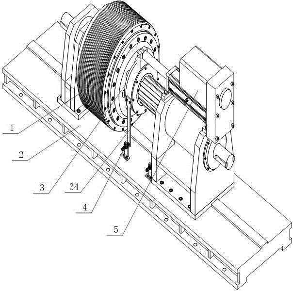
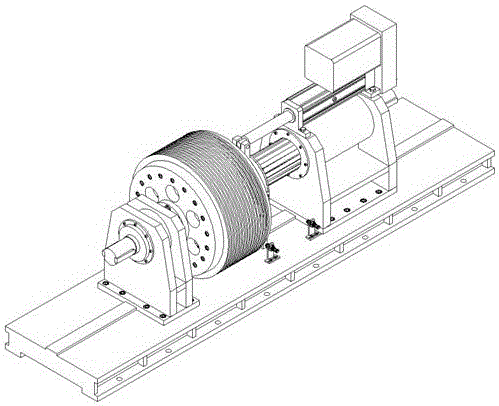
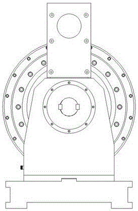
[0052] [22] As shown in the attached figure, a speed-regulating permanent magnet eddy current coupling includes: an active rotor mechanism 1, mainly composed of an eddy current rotor 6, an active yoke rotor 7, a cooling fin 23, an active shaft 11 and an active support frame 8, the eddy current rotor 6 and the active yoke rotor 7 adopt a wedge-shaped connection, interference fit, to ensure the coaxiality between the eddy current rotor 6 and the active yoke rotor 7, and both ends of the eddy current rotor 6 are connected to the active yoke The rotor 7 is connected by bolts, so that the two rotors are firmly connected during high-speed rotation, and the reliability of torque transmission is ensured; the driven rotor mechanism 3 is mainly composed of permanent magnets 13, magnetic pole inlays 14, driven yoke rotors 15, and load shafts 22 , a d...


PUM


Abstract

The invention relates to a speed-regulating type permanent magnet eddy current coupling, which comprises a driving rotor mechanism and a driven rotor mechanism, wherein the driving rotor mechanism is composed of an eddy current rotor, a driving yoke rotor, cooling fins, a driving shaft and the like, the eddy current rotor and the driving yoke rotor adopt wedge-shaped connection and interference fit so as to ensure the coaxiality between the rotors; and the driven rotor mechanism is composed of a permanent magnet, a magnetic pole inlay, a driven yoke rotor, a load shaft and the like, a taper angle between an internal conical surface of the eddy current rotor and an outer conical surface of the magnetic pole inlay is in the range of 1 degree to 179 degrees, the taper angle can be determined according to actual working conditions, and an air gap between the eddy current rotor and the permanent magnet is gradually reduced along with gradual increase in the meshing area of the eddy current rotor and the magnetic pole inlay, thereby enabling the torque transmission capacity of the coupling to be steadily increased. Compared with a disk type permanent magnet eddy current coupling, the permanent magnet eddy current coupling provided by the invention is more accurate in regulation for the output torque and the output speed. Compared with a cylinder type permanent magnet eddy current coupling, the permanent magnet eddy current coupling provided by the invention realizes soft start. The meshing area of the eddy current rotor and the magnetic pole inlay is regulated through an electric execution mechanism, thereby regulating the size of the air gap, and realizing accurate control for the torque transmission capacity.

Description

technical field [0001] The invention relates to a permanent magnet eddy current coupling. Background technique [0002] As we all know, the existing resources on the earth are becoming increasingly scarce and will eventually be exhausted. People are constantly exploring and seeking new energy sources. Although remarkable achievements have been made, they cannot replace existing energy sources. Therefore, saving energy and reducing consumption has become a social concern. Especially in the current stage of my country's economic development, energy saving and emission reduction are particularly important. According to statistics, in 2010, there were about 47 million fans and pumps in the country, and their power consumption accounted for more than 30% of the total industrial power consumption in the country. It is too long to damage the motor. Generally, the power of the driving motor is several times the actual rated power, and in some harsh environmental conditions, the ...

Claims


Application Information

Patent Timeline
IPC IPC(8): H02K16/00
Inventor 李贺俊刘永光刘丹
Owner BEIJING SINO POWER RUNZE ENVIRONMENTAL PROTECTIONCO
Features
  • Generate Ideas
  • Intellectual Property
  • Life Sciences
  • Materials
  • Tech Scout
  • Unparalleled Data Quality
  • Higher Quality Content
  • 60% Fewer Hallucinations
Learn More