CVT

A continuously variable transmission and jointless technology, which is applied to the transmission device, belt/chain/gear, transmission device parts, etc., can solve the problem of reduced driving force transmission efficiency, inability to narrow the gap between metal components 101, and difficulty in effectively acting on metal components by air 101 and other issues to achieve the effect of improving transmission efficiency

Active Publication Date: 2017-09-12
TOYOTA JIDOSHA KK
View PDF8 Cites 0 Cited by
  • Summary
  • Abstract
  • Description
  • Claims
  • Application Information

AI Technical Summary

Problems solved by technology

Therefore, there is a problem that slip occurs between the metal element 101 and the driving pulley KS at the position KD where the continuously variable transmission belt 100 is wound around the driving pulley KS, and the transmission efficiency of the driving force decreases.
That is, even if air is blown in the moving direction of the continuously variable transmission belt 100 to narrow the gap between the metal elements 101 in the stacking direction, since the outer shapes of the metal elements 101 are the same, the gaps between the metal elements 101 are small, and there is The blown air is difficult to effectively act on the metal element 101
In addition, there is a problem that, in the position KD where the continuously variable transmission belt 100 is wound around the driving pulley KS, in the metal element 101, the moving speed of the head 111 located on the outer peripheral side is lower than that on the inner peripheral side. If the moving speed of the main body part 112 is high, the gap between the metal elements 101 in the stacking direction cannot be reduced.

Method used


Image

  • CVT
  • CVT
  • CVT

Examples


no. 1 example

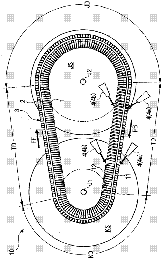
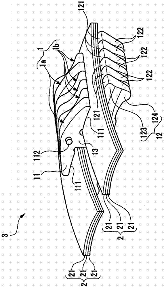
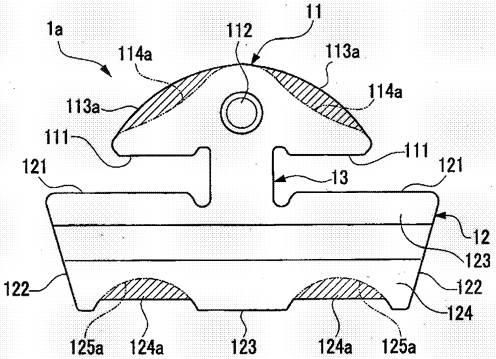
[0046] Such as Figure 6 As shown, the first embodiment is an example in which a first flange portion 113a is formed on the head portion 11 of one metal element 1a, and a second flange portion 124a is formed on the main body portion 12. On this basis, the continuously variable transmission While the belt 3 is moving from the driven pulley to the driving pulley (direction of arrow FB), from the injection ports 4a, 4b toward the first flange portion 113a and the second flange portion 113a along the moving direction of the continuously variable transmission belt 3. The two flange parts 124a blow fluid (lubricating oil) 4aw, 4bw. In this case, the first flange portion 113a and the second flange portion 124a formed on one metal element 1a protrude outward from the inclined side 113b and the arcuate side 124b of the other metal element 1b. Therefore, the fluids (lubricating oils) 4aw, 4bw blown from the ejection ports 4a, 4b of the fluid supply device 4 directly act on the first fl...

no. 2 example

[0048] Such as Figure 7 As shown, the second embodiment is an example in which the plate thickness t1 of one metal element 1a in the first embodiment is made larger than the plate thickness t2 of the other metal element 1b. By making the thickness t1 of one metal element 1a larger than the thickness t2 of the other metal element 1b, the inertial force of the one metal element 1a pressed by the fluids (lubricating oil) 4aw, 4bw can be increased. As a result, from the position where the fluid (lubricating oil) 4aw, 4bw is blown to the position where it is wound around the drive pulley KS, the metal layered in front of the metal element 1a on one side of the fluid (lubricating oil) 4aw, 4bw to be blown can be made The posture of the group of elements 1a, 1b is continuously maintained stable. In addition, a plurality of one metal element 1a having increased plate thickness t1 may exist, and may be arranged at an appropriate interval between the other metal element 1b.

no. 3 example

[0050] Such as Figure 8 As shown, the third embodiment is an example in which a first groove portion 114a is formed in the head portion 11 of one metal element 1a, and a second groove portion 125a is formed in the main body portion 12. 3 While moving from the driven pulley to the driving pulley (direction of arrow FB), from the injection ports 4a and 4b to the first groove portion 114a and the second groove portion along the moving direction of the continuously variable transmission belt 3 125a blows fluid (lubricating oil) 4aw, 4bw. In this case, the first groove part 114a and the second groove part 125a formed in one metal element 1a are recessed inwardly than the inclined side 114b and the arc side 125b of the other metal element 1b. Therefore, the fluids (lubricating oils) 4aw, 4bw blown from the ejection ports 4a, 4b of the fluid supply device 4 directly act on the metal element 1a stacked in front of one of the first grooves 114a and the second grooves 125a. The back ...


PUM


Abstract

This continuously variable transmission (10) is obtained by winding, around a drive sheave (KS) and a driven sheave (JS), a continuously variable transmission belt (3) in which a plurality of metal elements (1) are stacked and supported on an endless ring (2). In at least one of the metal elements (1), flange parts (113a, 124a) are formed on a head part (11) positioned at an outer peripheral side of the endless ring (2) and a trunk part (12) positioned at an inner peripheral side of the endless ring (2). The continuously variable transmission (10) is provided with a fluid supply device (4) which, during movement of the continuously variable transmission belt (3) from the driven sheave (JS) to the drive sheave (KS), sprayed lubricating oil (4aw, 4bw) in a movement direction (the direction of arrow FB) of the continuously variable transmission belt (3), towards the flange parts (113a, 124a).

Description

technical field [0001] The present invention relates to a continuously variable transmission including a belt for a continuously variable transmission in which a plurality of metal elements are supported endlessly. Background technique [0002] For example, if Figure 11 As shown, in the continuously variable transmission 200 , the continuously variable transmission belt 100 constituted by stacking and supporting a plurality of metal elements 101 by the endless ring 102 is wound around the driving pulley KS and the driven pulley JS. The driving pulley KS and the driven pulley JS each include a conical plate-shaped fixed pulley and a movable pulley. Each movable pulley of the continuously variable transmission 200 moves in the directions of the axes J1 and J2 to change the radius of rotation of the continuously variable transmission belt 100 wound thereon, thereby continuously changing the speed from high speed to low speed. [0003] Generally, when the continuously variable...

Claims


Application Information

Patent Timeline
Patent Type & Authority Patents(China)
IPC IPC(8): F16H9/12F16G5/16
CPCF16H9/18F16G5/16F16H57/046F16H57/0489
Inventor 佐佐丰海安藤悟石井良和
Owner TOYOTA JIDOSHA KK
Why Eureka
Try Eureka