Vibrating Suction Bucket Foundation Leveling Device

A barrel-shaped foundation and leveling device technology, applied in infrastructure engineering, construction and other directions, can solve the problems of low control accuracy, inclination of suction barrel-shaped foundations, and high requirements for barrel-shaped basic structures, so as to weaken frictional resistance and improve The effect of deep penetration and simple overall structure

Active Publication Date: 2016-05-04
ZHEJIANG UNIV +1
View PDF5 Cites 0 Cited by
  • Summary
  • Abstract
  • Description
  • Claims
  • Application Information

AI Technical Summary

Problems solved by technology

[0003] Due to the difference in geological conditions and the uncertainty of the construction process, the suction barrel foundation may be tilted, and the settlement resistance of the barrel foundation will be increased under a certain inclination state, and in severe cases, the barrel foundation may also be caused The problem of not being able to sink to the predetermined position
[0004] At present, there are three main methods for controlling the inclination of barrel foundations: (1) Manual control, which artificially judges the inclination of the suction barrel foundation, and then starts the operating equipment to level the foundation. This method has low control accuracy and cannot Guarantee the construction quality; (2) Multi-chamber automatic leveling method of barrel foundation, automatically level the barrel foundation by controlling the vacuum degree of different chambers, this method has higher requirements on the barrel foundation structure; (3) Abroad There is a patented technology of installing nozzles at the end of the barrel skirt, which can control the inclination angle of the barrel foundation during the sinking process and reduce the sinking resistance of the barrel skirt by controlling the nozzles at different angles to spray high-pressure water and gas

Method used


Image

  • Vibrating Suction Bucket Foundation Leveling Device
  • Vibrating Suction Bucket Foundation Leveling Device
  • Vibrating Suction Bucket Foundation Leveling Device

Examples


Embodiment Construction

[0022] The present invention will be further described below in conjunction with the accompanying drawings and embodiments.

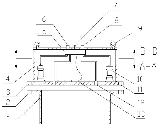
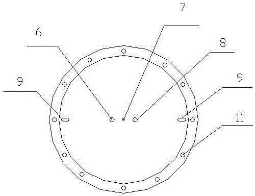
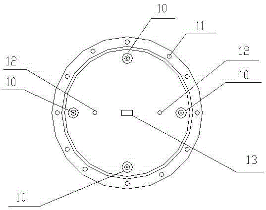
[0023] Such as Figure 1 to Figure 5 As shown, the present invention comprises base plate 3, bung 4, vibrating mechanism 10, two-way angle sensor 13 and electromagnetic valve control module 5; Base plate 3 is covered with bung 4, is positioned at base plate 3 in bung 4 and is evenly distributed on the same circumference There are a plurality of vibrating mechanisms 10, and two base plate negative pressure ports 12 are opened on the base plate 3 located in the plurality of vibrating mechanisms 10, and a bidirectional angle sensor 13 is installed in the center of the base plate; 7 and bung cover negative pressure port 8, positive pressure port 6 are respectively connected with a plurality of electromagnetic valve 16 input ports in the electromagnetic valve control module 5, and a plurality of electromagnetic valve 16 output ports are respectively connecte...


PUM


Abstract

The invention discloses a vibrating type leveling device for suction bucket foundation. A bucket cover is covered on a bottom plate, a plurality of vibrating mechanisms are uniformly distributed at the same periphery of the bottom plate which is positioned in the bucket cover; two bottom plate negative-pressure openings are formed in the bottom plate in the vibrating mechanisms; a two-way angle sensor is mounted on the center of the bottom plate; a positive pressure opening, a wire outlet and a bucket cover negative pressure opening are formed in an upper surface of the bucket cover, the positive pressure opening is connected with a plurality of solenoid valve input openings in a solenoid valve control module respectively, a plurality of solenoid valve output openings are connected to pneumatic connectors of the respective vibrating mechanisms respectively; the bucket cover negative pressure opening is connected with the two bottom plate negative-pressure openings through the solenoid valve control module; a signal wire of the two-way angle sensor and a control wire of each solenoid valve are connected to a programmable logic controller through the wire outlet in the bucket cover. The vibrating type leveling device not only can control the gesture of the bucket foundation, but also can weaken friction resistance between the bucket foundation and a soil body, improves penetration depth, and can detect the inclination degree of the bucket foundation in real time and can control the penetration gesture of the bucket foundation.

Description

technical field [0001] The invention relates to a barrel-shaped foundation leveling device, in particular to a vibration-type suction-type barrel-shaped foundation leveling device. Background technique [0002] In July 1994, Statoil Corporation adopted a new type of foundation different from the traditional pile foundation—barrel foundation—for the first time on a large jacket platform. The foundation is a steel large-diameter cylindrical structure with a closed top and an open bottom. It uses negative pressure to empty the water in the barrel, and a pressure difference is generated inside and outside the barrel, so that the barrel-shaped foundation penetrates into the design depth. Since the appearance of the suction barrel foundation, its advantages such as low cost, short construction time, light weight, easy installation and reusability in offshore construction, etc. are gradually being recognized by the engineering community in the world. [0003] Due to the difference...

Claims


Application Information

Patent Timeline
Patent Type & Authority Patents(China)
IPC IPC(8): E02D35/00
CPCE02D35/005
Inventor 朱斌黄锦舒邢月龙郭勇
Owner ZHEJIANG UNIV
Why Eureka
Try Eureka