
A method for calculating the tooth-cutting motion trajectory of a split equal-base bevel gear

A technology of motion trajectory and calculation method, applied in the field of bevel gear cutting, which can solve problems such as the inability of machine tools to process

Active Publication Date: 2020-11-17
HENAN UNIV OF SCI & TECH
View PDF8 Cites 0 Cited by
  • Summary
  • Abstract
  • Description
  • Claims
  • Application Information

AI Technical Summary

Problems solved by technology

[0005] The purpose of the present invention is to solve the problem that the machine tool cannot process when the rotation center of the equibasic bevel gear split wheel blank falls outside the machine tool and cannot coincide with a certain rotation axis of the machine tool on a general-purpose numerical control machine tool, and provides A gear cutting method for split equal-base bevel gears

Method used


Image

  • A method for calculating the tooth-cutting motion trajectory of a split equal-base bevel gear
  • A method for calculating the tooth-cutting motion trajectory of a split equal-base bevel gear
  • A method for calculating the tooth-cutting motion trajectory of a split equal-base bevel gear

Examples


Embodiment Construction

[0093] As shown in the figure, the specific implementation method is as follows:

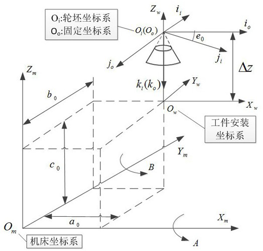
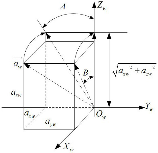
[0094] Taking the processing of the large wheel in the gear pair shown in Table 1 as an example, a method for calculating the tooth cutting motion track of the split equal base bevel gear of the present invention will be further described in detail in conjunction with the accompanying drawings. In the present embodiment, the number of processed teeth of the bull wheel split body is 3.

[0095] Table 1 Basic geometric parameters of gear pair

[0096]

[0097] Step 1: Solve the included angle e for different processing sequences and different tooth surfaces

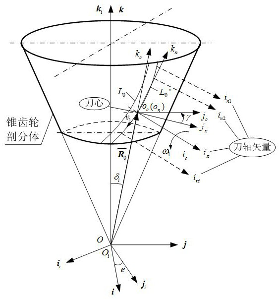
[0098] In the equibasic bevel gear cutting coordinate system (attached figure 1 ), the wheel blank coordinate system Axis and Space Fixed Coordinate System The value of the included angle e of the axis determines the relative positional relationship of each convex and concave tooth surface under fixed spatial coordinates. According ...


PUM


Abstract

Provided in the invention is a method for calculating the gear cutting movement trajectory of a splitting type equal-base bevel gear wheel. On the basis of the theory of the equal-base circular-curvebevel gear wheel, a splitting type gear cutting processing coordinate system is established according to characteristics of tooth surface forming and each instantaneous cutter position attitude of thetooth surface is analyzed; calculation and coordinate conversion are carried out by a cutter axis vector and a cutter core coordinate, so that a cutter position under a wheel blank coordinate systemis obtained. Each instantaneous cutter position during gear cutting processing is calculated by combining the structural layout of a general machine tool and an installation position relationship between a split wheel blank and a machine tool; and then post-processing is carried out to obtain an expression function of a machine tool motion coordinate during numerical control gear cutting is obtained. According to the invention, a problem that processing can not be carried out when the revolution center of the split type wheel blank of the equal-base bevel gear wheel falls beyond the general numerical control machine tool and thus is not overlapped with a certain revolution axis of the machine tool is solved.

Description

technical field [0001] The invention relates to a bevel gear cutting method, in particular to a method for calculating the gear cutting motion track of a split equal-base bevel gear. Background technique [0002] Extra-large bevel gears are key components of large-scale key equipment and are irreplaceable in national economy and national defense construction. At present, the extra-large bevel gears used in large-scale key equipment are all straight bevel gears. When the diameter of the large wheel of the gear pair is greater than 3000mm, because the structural characteristics of the overall wheel blank are annular thin-walled parts, the rigidity of the integral large wheel structure is poor, and the processes such as processing, transportation, and assembly are easily deformed, and the overall processing is often affected. Limited to the specifications of the existing gear-making equipment, it is difficult to carry out road and rail transportation after processing. Therefor...

Claims


Application Information

Patent Timeline
Patent Type & Authority Patents(China)
IPC IPC(8): G05B19/19
CPCG05B19/19G05B2219/35349
Inventor 王斌冯佩瑶何云鹏孙逊
Owner HENAN UNIV OF SCI & TECH
Learn More