
Welding method for double bevel groove (DHV) weld joints

A welding method and bevel technology, applied in welding equipment, arc welding equipment, manufacturing tools, etc., can solve the problems of reduced weld strength, incomplete fusion between layers, and incomplete cleaning between layers of welds, so as to ensure root cleaning Quality, the effect of ensuring welding quality

Inactive Publication Date: 2016-01-06
CRRC TANGSHAN CO LTD
View PDF8 Cites 8 Cited by
  • Summary
  • Abstract
  • Description
  • Claims
  • Application Information

AI Technical Summary

Problems solved by technology

[0005] 1. When cleaning the root, because the groove angle of the weld on the cleaning side is small, the accessibility of the straight grinder is limited, resulting in incomplete cleaning between the weld layers, leaving impurities inside the weld, resulting in re- Welding defects such as lack of fusion between layers are prone to occur during welding
[0006] 2. The groove angle of the weld seam after root cleaning is smaller, which cannot meet the requirements of the EN15085-3 standard that the groove angle of the weld seam is within the range of 50°-60°, which makes the welding arc more difficult Contacting the root of the groove and the upper surface of the groove, therefore, it is easy to produce no fusion at the root of the weld and the upper surface of the weld, and the welding residual stress is unevenly distributed, resulting in poor weld quality and reduced weld strength
[0007] Therefore, the DHV type weld seam welding process of the prior art cannot effectively guarantee the quality of root cleaning and the welding quality after root cleaning

Method used


Image

  • Welding method for double bevel groove (DHV) weld joints
  • Welding method for double bevel groove (DHV) weld joints
  • Welding method for double bevel groove (DHV) weld joints

Examples


Embodiment Construction

[0040] In order to make the purpose, technical solutions and advantages of the embodiments of the present invention clearer, the technical solutions in the embodiments of the present invention will be clearly and completely described below in conjunction with the drawings in the embodiments of the present invention. Obviously, the described embodiments It is a part of embodiments of the present invention, but not all embodiments. Based on the embodiments of the present invention, all other embodiments obtained by persons of ordinary skill in the art without creative efforts fall within the protection scope of the present invention.

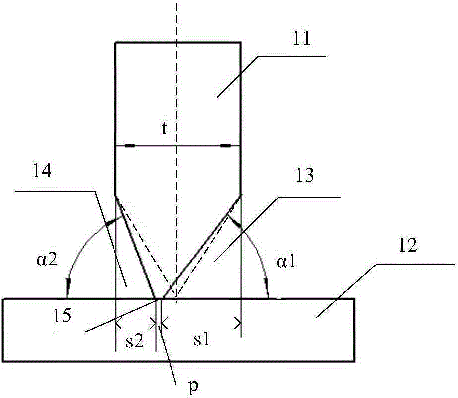
[0041] figure 2 Schematic diagram of the structure of the DHV type weld provided by the embodiment of the present invention. Such as figure 2 As shown, the groove 13 of the first side weld of the welding single piece 11 and the groove 14 of the second side weld are asymmetrical structures, and the angle α1 of the groove 13 of the first side we...


PUM

PropertyMeasurementUnit
thicknessaaaaaaaaaa

Abstract

The invention provides a welding method for double bevel groove (DHV) weld joints. The method is applied to a single welding workpiece. The bevel of the first side weld joint of the single workpiece is not symmetrical to the bevel of the second side weld joint of the single workpiece; the angle of the bevel of the first side weld joint is smaller than the angle of the bevel of the second side weld joint; and the depth of the bevel of the first side weld joint is larger than the depth of the bevel of the second side weld joint. The method comprises the steps that the first side weld joint is welded, wherein the angle of the bevel of the first side weld joint is larger than or equal to 50 degrees, and is smaller than or equal to 60 degrees; after the first side weld joint is welded, back gouging and back gouging penetration testing are performed on the second side weld joint; and after back gouging penetration testing is passed, the second weld joint subjected to back gouging is welded. According to the welding method for the DHV weld joints provided by the embodiment of the invention, the back gouging quality and the welding quality can be effectively ensured.

Description

technical field [0001] Embodiments of the present invention relate to welding technology, in particular to a welding method for double-sided bevel butt (Double bevel butt, Double HV, DHV for short) type welds. Background technique [0002] In subway rail vehicles, DHV type welds are generally used for assembly and welding between the coupler panel, the upper cover and the lower cover. [0003] At present, the commonly used DHV type welds are mostly double-sided symmetrical weld structures. figure 1 It is a structural schematic diagram of a DHV weld seam in the prior art. Such as figure 1 As shown, the weld structure between the coupler face plate 1 and the upper cover plate 3 is a symmetrical DHV type, that is, the groove angles of the weld seam 2 and the weld seam 4 are equal. For example, if the thickness of the coupler face plate t=25mm, the corresponding weld Seam 2 and weld 4 are 12.5HV / 12.5HV, blunt side p=1mm, then the groove angle on both sides is α=60°. When wel...

Claims


Application Information

Patent Timeline
Patent Type & Authority Applications(China)
IPC IPC(8): B23K9/235B23K9/02
CPCB23K9/235B23K9/02
Inventor 姚肖洁桂洪利黄少东吴振华李玉璐侯振国高学准
Owner CRRC TANGSHAN CO LTD
Learn More