
Power cable reel rack storage device

A technology for power cables and storage devices, applied in packaging, external frames, display hangers, etc., can solve the problems of low utilization rate, warehouse management, high maintenance costs, and a large number of warehouses, so as to save occupied area and improve The effect of buttoning success rate and improving reliability

Inactive Publication Date: 2016-01-06
STATE GRID SHANDONG ELECTRIC POWER COMPANY WEIFANG POWER SUPPLY +1
View PDF6 Cites 2 Cited by
  • Summary
  • Abstract
  • Description
  • Claims
  • Application Information

AI Technical Summary

Problems solved by technology

Since there is no special storage device for storing power cable racks, power companies currently place various types of power cable racks in sequence on the warehouse floor. Although this solves the storage problem, each power cable The racks all take up one floor area, resulting in the need for a lot of storage
Contrary to the power cable reel rack, other power equipment such as transformers, compensation capacitors, etc. have cuboid wooden packing boxes, which can be stacked up and down, so that there is no need for too much warehouse space, so it is purely for storing power cable reels The utilization rate of the expanded warehouse is very low, resulting in high warehouse management and maintenance costs

Method used


Image

  • Power cable reel rack storage device
  • Power cable reel rack storage device
  • Power cable reel rack storage device

Examples


Embodiment Construction

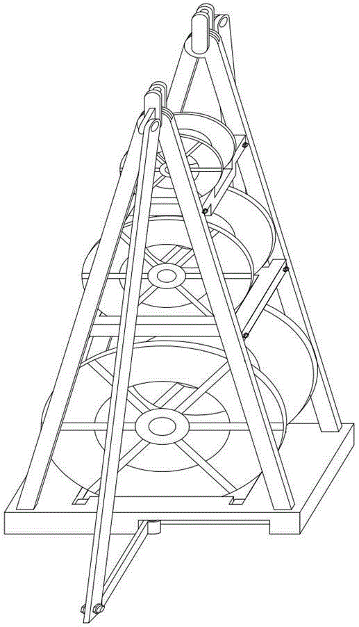
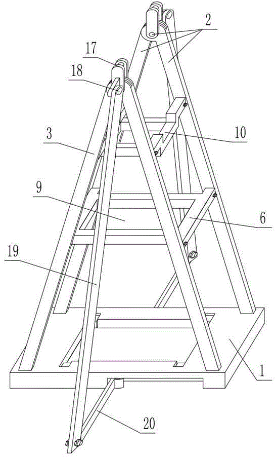
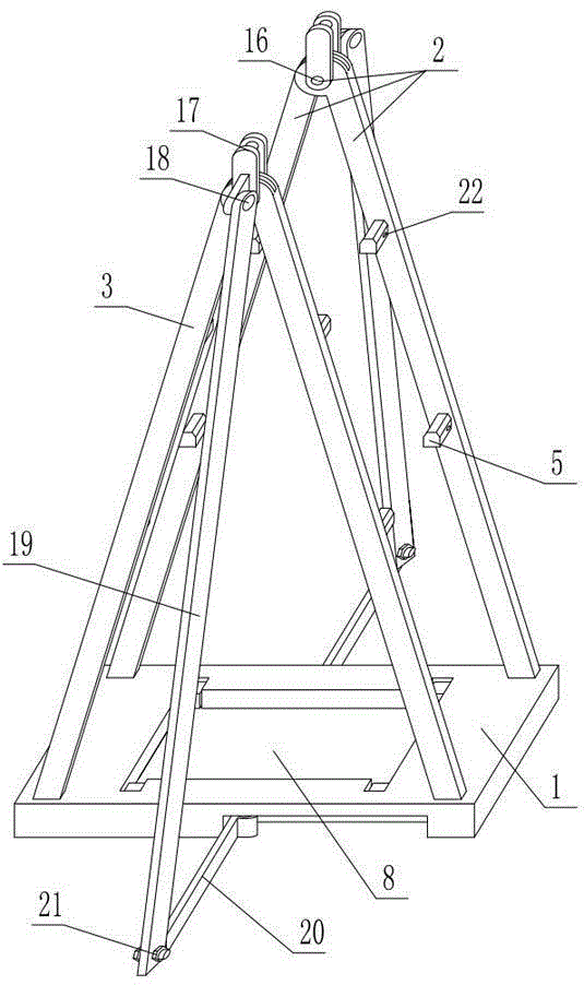
[0045] As shown in the figure, the power cable tray storage device includes a base 1 and two hinge frames 2 arranged on both sides of the base 1. The hinge frame 2 includes a support arm 3 whose upper end is hinged together by a hinge shaft 16. The hinge shaft 16 A half ring 17 is fixedly connected between the two ends. The lower end of the support arm is clamped on the four corners of the base through the clamping parts 4, and the corresponding cross arm 5 is fixed at the height of the support arm 3, and the upper frame 6 supported by the cross arm is arranged between the two hinges. Lock together with the cross arm 5 through the locking piece 7 . The middle part of the base 1 is provided with a base hole 8 for clamping a power cable tray, the upper shelf 6 can be contained in the base hole 8, and the middle part of the upper shelf is provided with an upper shelf hole 9 for snapping a power cable tray.

[0046] The main structure of the power cable tray storage device is a b...


PUM


Abstract

The invention discloses a power cable reel rack storage device. The power cable reel rack storage device comprises a base and two hinged frames arranged on the two sides of the base. Each hinged frame comprises supporting arms, wherein the upper ends of the supporting arms are hinged together through a hinged shaft. A semi-ring is fixedly connected between the two ends of each hinged shaft. The lower ends of the supporting arms are clamped on the four corners of the base through clamping parts. Cross arms are correspondingly and fixedly arranged at the equal-height positions of the supporting arms. An upper frame which is supported by the cross arms is arranged between the two hinged frames. The upper frame and the cross arms are locked together through locking parts. A base hole used for clamping power cable reel racks is formed in the middle of the base. The upper frame can be contained in the base hole. An upper frame hole used for clamping the power cable reel racks is formed in the middle of the upper frame. The power cable reel rack storage device has the advantages that the structure is reasonable, the device can be assembled quickly when used, up-down stacking of the horizontally-placed power cable reel racks can be achieved, and the power cable reel racks are firmly placed and are easy to take and place; moreover, the device can be dismounted and stored conveniently when not in use and is small in occupied space and particularly suitable for quickly storing a large number of power cable reel racks in a warehouse with a limited space.

Description

technical field [0001] The invention relates to a power cable reel storage device. Background technique [0002] The power cable is the carrier of power transmission. According to different uses, power cables can be roughly divided into bare wires and cored wires. Bare wires are mainly used for high-altitude power transmission, and cored wires are mainly used for underground power transmission. With the development of modern urban power transmission, underground power transmission has become the main means of urban power transmission today. Correspondingly, the application of cored wire is also increasing. Because the cored wire is to be laid underground, it must ensure sufficient insulation performance, which requires a thicker insulating layer, so the cored wire is generally much thicker than the bare wire. [0003] At present, power cables are generally wound on power cable reels for packaging, transportation and storage. The power cable reel generally includes two co...

Claims


Application Information

Patent Timeline
IPC IPC(8): B65D6/22
CPCA47F5/10B65D61/00B65D85/66B65H49/38
Inventor 张秀华孙华勇赵杉赵日凯李仁飞张峰王晓辉王兰兰刘海鹏何强刘凤刚祖金国徐振宇刘伟刘伟光张璐赵永怡高杨王永新姚中旺
Owner STATE GRID SHANDONG ELECTRIC POWER COMPANY WEIFANG POWER SUPPLY
Learn More