

Thread winding mechanism system of an automatic silk reeling machine
A mechanism system and silk reeling machine technology, applied in the direction of silk reeling, etc., can solve the problems of affecting the efficiency of cocoon adding hopper to transfer the cocoon, affecting the cocoon thread of the thread, reducing work efficiency, etc., to improve threading efficiency and structure Simple, Efficiency-Enhancing Effects
- Summary
- Abstract
- Description
- Claims
- Application Information
AI Technical Summary
Problems solved by technology
Method used
Image

Examples
Embodiment 1
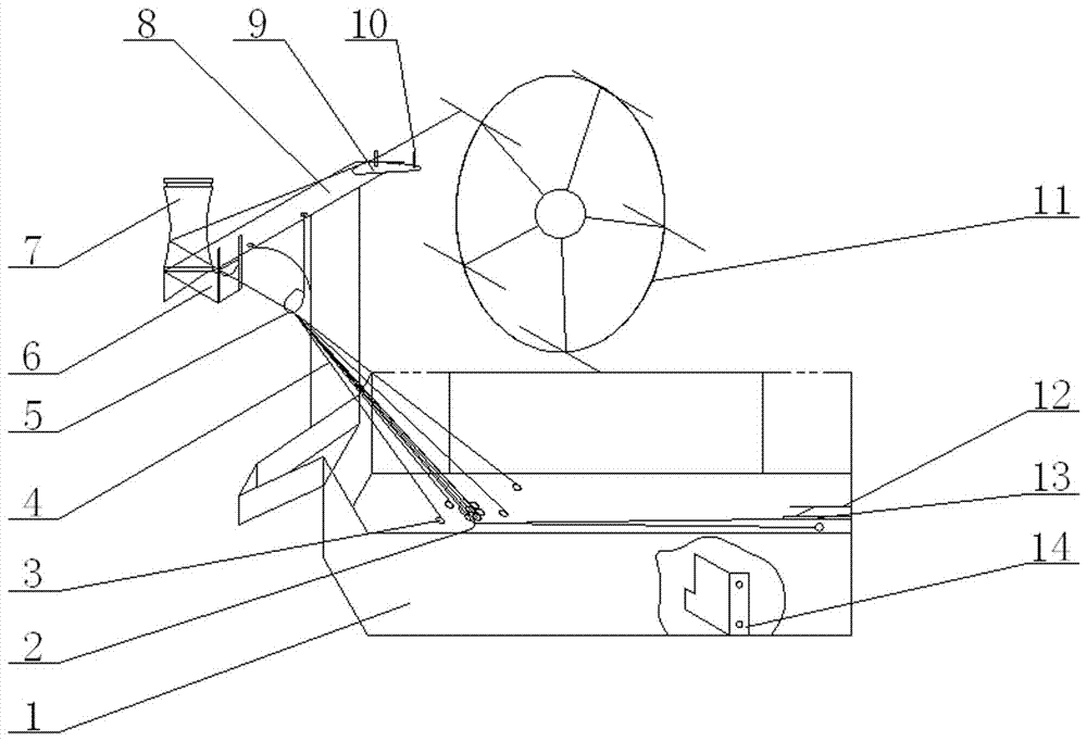
[0021] figure 1 As shown, a thread rolling mechanism system of an automatic silk reeling machine includes a thread straightening pot 1, a thread thread rolling machine 11, a thread guide roller 7, a U-shaped thread collection plate 6, a support table 8, a thread guide hook 2 and a needle 12 ; The support platform 8 is installed at the threaded cocoon exit of the threading pot 1; the thread guide roller 7 and the U-shaped thread collecting plate 6 are installed on the support table 8; The table 8 is on the same side; it is characterized in that: the thread-collecting hook 5 is installed on the support table 8, and the center of the thread-collecting hook 5 is on the same vertical plane as the center of the circle of the U-shaped thread-collecting plate 6. The height difference of the center of the circle is -5 centimeters; The deflector 14 is installed on the inner wall of the Lixu pot 1, and the included angle between it and the inner wall is 50°, and the distance from the Lix...
Embodiment 2
[0024] figure 1 As shown, a thread rolling mechanism system of an automatic silk reeling machine includes a thread straightening pot 1, a thread thread rolling machine 11, a thread guide roller 7, a U-shaped thread collection plate 6, a support table 8, a thread guide hook 2 and a needle 12 ; The support platform 8 is installed at the threaded cocoon exit of the threading pot 1; the thread guide roller 7 and the U-shaped thread collecting plate 6 are installed on the support table 8; The table 8 is on the same side; it is characterized in that: the thread-collecting hook 5 is installed on the support table 8, and the center of the thread-collecting hook 5 is on the same vertical plane as the center of the circle of the U-shaped thread-collecting plate 6. The height difference of the center of the circle is -3 centimeters; the deflector 14 is installed on the inner wall of the Lixu pot 1, and the included angle between it and the inner wall is 55°, and the distance from the bot...
Embodiment 3
[0027] figure 1 Shown: a thread rolling mechanism system of an automatic silk reeling machine, including thread straightening pot 1, thread rolling machine 11, thread guiding roller 7, U-shaped thread collecting plate 6, support table 8, thread guiding hook 2 and needle 12 ; The support platform 8 is installed at the threaded cocoon exit of the threading pot 1; the thread guide roller 7 and the U-shaped thread collecting plate 6 are installed on the support table 8; The table 8 is on the same side; it is characterized in that: the thread-collecting hook 5 is installed on the support table 8, and the center of the thread-collecting hook 5 is on the same vertical plane as the center of the circle of the U-shaped thread-collecting plate 6. The height difference of the center of the circle is -2 centimeters; the deflector 14 is installed on the inner wall of the cooking pot 1, and the angle formed between it and the inner wall is 60°, and the distance from the bottom plate of the ...
PUM
 Abstract
Description
Claims
Application Information