Main reducer assembly with two end input function

A main reducer and front-end input technology, which is applied in the direction of gear transmission, belt/chain/gear, mechanical equipment, etc., can solve the problem that the input at one end of the main reducer assembly cannot meet the performance requirements, and achieve outstanding substantive features, The effect of simple structure

Inactive Publication Date: 2016-01-06
SHANDONG PENGXIANG AUTOMOBILE
View PDF5 Cites 0 Cited by
  • Summary
  • Abstract
  • Description
  • Claims
  • Application Information

AI Technical Summary

Problems solved by technology

[0005] The purpose of the present invention is to overcome the above-mentioned deficiencies in the prior art, and provide a final drive assembly that allows input at both ends; it mainly solves the problem that the input at one end of the existing final drive assembly cannot meet the performance requirements

Method used


Image

  • Main reducer assembly with two end input function
  • Main reducer assembly with two end input function

Examples


Embodiment 1

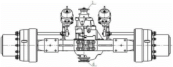
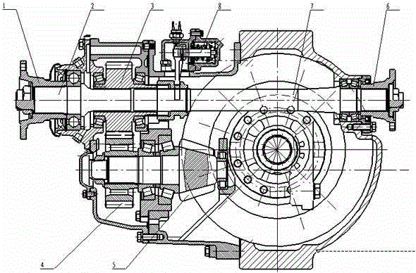
[0012] Example 1, see figure 1 , 2 , select the front input shaft 2 and the rear input shaft 7 of appropriate specifications, install the front input flange 1 outside the front end of the front input shaft 2, and install the rear input flange 6 outside the rear end of the rear input shaft 7; The front input shaft 2 is connected with the driving cylindrical gear 3 through a spline, and the driving cylindrical gear 3 meshes with the driven cylindrical gear 4 on the main cone 5, and finally the power is transmitted to the tire; the rear input shaft 7 is connected with the differential gear through a spline. The lock 8 is connected, the rear input shaft 7 is in contact with the driving cylindrical gear 3 through the shaft hole, and there is no rigid connection. When the differential lock 8 moves to the left, it can be connected with the driving cylindrical gear 3 and the rear input shaft through the spline at the same time. 7 are connected to each other to form the main reducer a...


PUM


Abstract

The invention discloses a main reducer assembly with the two end input function. The main reducer assembly with the two end input function is characterized by comprising a front-end input shaft (2) and a rear-end input shaft (7), wherein a front-end input flange (1) and a rear-end input flange (6) are arranged outside the front-end input shaft (2) and the rear-end input shaft (7) respectively; the front-end input shaft (2) is connected with a driving cylindrical gear (3) through a spline and the driving cylindrical gear (3) is meshed with a driven cylindrical gear (4) on a main cone (5); the rear-end input shaft (7) is connected with a differential lock (8) through a spline, the rear-end input shaft (7) makes contact with the driving cylindrical gear (3) through the cooperation of an axial hole, and rigid connection is avoided. By the adoption of the main reducer assembly, the two end input function is achieved, power is supplied to the front end through an engine and a transmission, and power is supplied to the rear end through a speed reducer; and on the premise that a clutch is not available, according to the requirements, when input through the front end, power is not output through the rear end, and when input through the rear end, power is allowed to be output through the front end, and only a neutral gear needs to be shifted by the transmission at this moment.

Description

Technical field: [0001] The invention relates to the technical field of vehicle axles, in particular to a final reducer assembly that allows input at both ends; it is mainly used for mine vehicle axles and special vehicle axles. Background technique: [0002] At present, for special vehicles, such as vehicles for bridge erecting machines, the entire vehicle has only one driving axle. , it is not allowed to turn around. At this time, the engine and gearbox are needed to drive the whole vehicle to leave. [0003] When the reducer drives the vehicle, the gearbox can be placed in neutral, so the end connected to the gearbox is allowed to rotate; when the engine and gearbox drive the vehicle, the shaft driving the reducer is not allowed to rotate, which can save a clutch. [0004] The main reducer assembly currently used is input at one end. Even if the middle axle allows input from both ends, one end slips and the other end has no power output, or both ends rotate at the same t...

Claims


Application Information

Patent Timeline
Patent Type & Authority Applications(China)
IPC IPC(8): F16H1/22
CPCF16H1/222
Inventor 尚国瑞胡顺安李兴瑞马京帅吴来君
Owner SHANDONG PENGXIANG AUTOMOBILE
Why Eureka
Try Eureka