
Lubricating oil circuit system and planetary gear reducer for aircraft planetary gear reducer

A planetary gear deceleration, lubricating oil circuit technology, applied in the direction of gear lubrication/cooling, belt/chain/gear, mechanical equipment, etc., can solve the problem of not centralized discharge of lubricating oil, pollution, etc., and achieve the maximum material and structure. effect of chemical utilization

Inactive Publication Date: 2016-05-04
CENT SOUTH UNIV
View PDF7 Cites 0 Cited by
  • Summary
  • Abstract
  • Description
  • Claims
  • Application Information

AI Technical Summary

Problems solved by technology

[0004] According to the understanding of the existing planetary gear reducer, the lubricating oil after the lubrication of its various parts is not discharged in a concentrated manner, and there is pollution to other parts, and the aircraft engine has stricter requirements for this

Method used


Image

  • Lubricating oil circuit system and planetary gear reducer for aircraft planetary gear reducer
  • Lubricating oil circuit system and planetary gear reducer for aircraft planetary gear reducer
  • Lubricating oil circuit system and planetary gear reducer for aircraft planetary gear reducer

Examples


Embodiment 1

[0033] Example 1: Aircraft planetary gear reducer lubricating oil circuit system

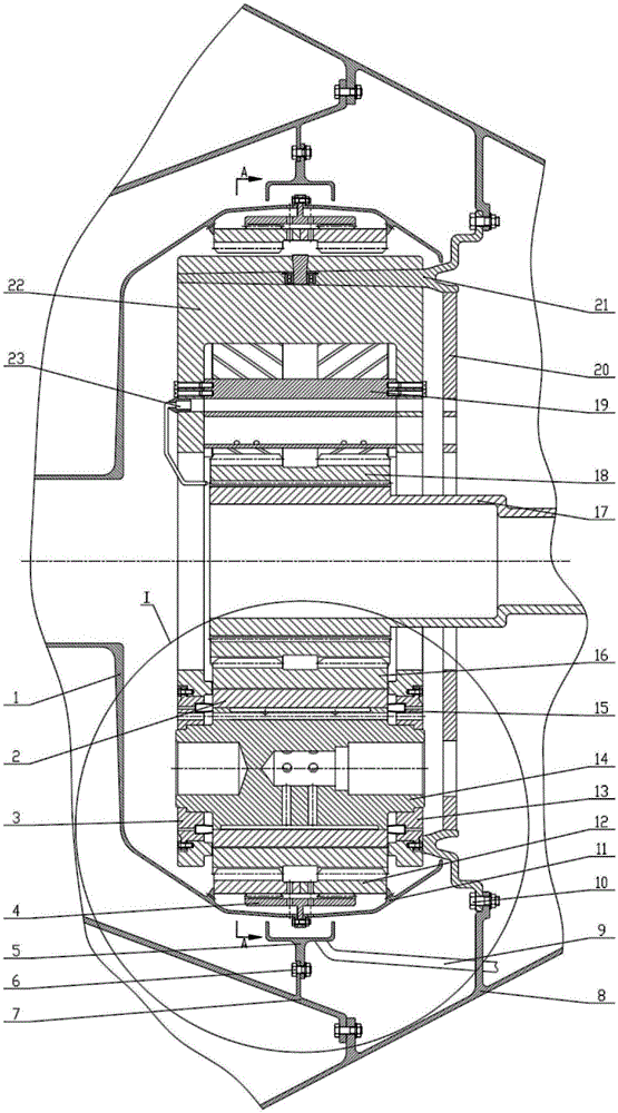
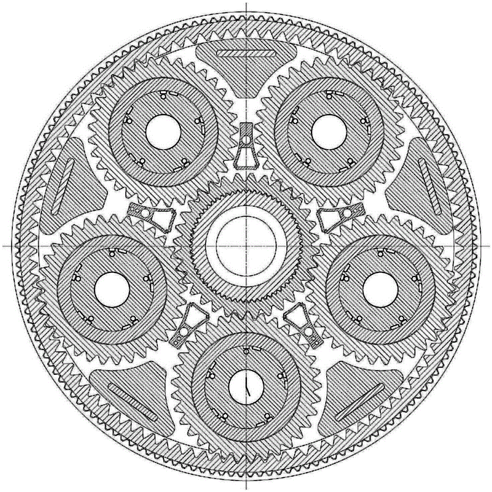
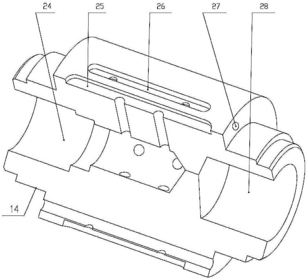
[0034] Such as Figure 1~5 As shown, an embodiment of the lubricating oil circuit system of the planetary gear reducer of the aircraft of the present invention is based on the improvement of the structure of the components in the existing planetary gear reducer, so that it adds an oil passage structure with lubrication function. Including sliding bearing lubricating oil circuit, gear lubricating oil circuit, inner gear lubricating oil circuit and oil collecting groove 5 fixed on the aircraft casing A7. The sliding bearing lubricating oil circuit includes a stepped hole arranged at one end of the planetary wheel shaft 14 for oil intake 24. A plurality of oil inlet grooves 25 evenly distributed on the outer circumference of the planetary wheel shaft 14 and communicated with the stepped hole 24, a plurality of oil outlet grooves 26 evenly distributed on the outer circumference of the planetary wheel s...

Embodiment 2

[0042] Embodiment 2: Planetary gear reducer using the above-mentioned planetary gear reducer lubricating oil circuit system

[0043] Such as figure 1 with figure 2 As shown, a planetary gear reducer of the present invention adopts a transmission mode of input from the sun gear 18 and output from the ring gear 12. The input shaft 17 and the sun gear 18 are connected by splines, and the power is transmitted from the input shaft 17 to The sun gear 18 and the planet gear 16 are mounted on the planet wheel shaft 14 of the planet carrier 22. The planet wheel shaft 14 is provided with a five-oil wedge sliding bearing 2. The two ends of the planet wheel shaft 14 are respectively positioned by the left baffle 3 and the right baffle 13, and The fixing of the planet carrier 22 in the vertical direction is completed by the support structure 21. The support structure 21 is fixed to the aircraft receiver B8 by bolts B10. The middle of the support structure 21 is provided with an oil baffle 20;...


PUM


Abstract

The invention discloses a lubricating oil way system of an airplane planetary gear reduction box. The lubricating oil way system comprises a sliding bearing lubricating oil way, a gear lubricating oil way, an inner gear ring lubricating oil way and an oil collection tank fixed to an airplane casing A. A sliding bearing is lubricated in the manners that oil flows in a stepped hole in a planetary gear axle and oil flows out from the axle and the end face. A planetary gear and a sun gear are lubricated in the manner that oil is injected to the gear engagement position of a gear lubricating structure. An inner gear ring is lubricated in the manner that oil is introduced into the inner gear ring through engagement of the inner gear ring and the lubricated planetary gear, some oil flows out of the two engaged end faces of the gears and drained into the oil collection tank through left and right output structures, and the other oil is drained into the oil collection tank through two columns of holes formed in the inner gear ring. According to the reduction box, the requirement for lubrication can be met, the space, materials and structures can be sufficiently utilized to the maximum extent, the lubricating oil is finally and completely drained in a concentrated manner and will not pollute other portions, and the lubricating oil can be recycled.

Description

Technical field [0001] The invention belongs to the field of mechanical transmission equipment, and particularly relates to an aircraft planetary gear reducer lubricating oil circuit system and a planetary gear reducer. Background technique [0002] In the turbofan engine of a traditional civil aircraft, the fan is directly driven by a low-pressure turbine. Due to the limitation of strength and blade tip tangential speed, the speed of the fan is low, generally 4000-5500r / min, while the low-pressure turbine has a higher speed. High, generally 8000r / min. This presents an obvious lack of efficiency matching, that is, the speed of the fan and the speed of the low-pressure turbine are not optimal. To solve this problem, Pratt & Whitney has developed a gear-driven turbofan engine, which adds a planetary gear reducer after the fan. [0003] Because of the small space and compact structure of the planetary gear reducer installed in the aircraft engine, it is very difficult to introduce a...

Claims


Application Information

Patent Timeline
Patent Type & Authority Patents(China)
IPC IPC(8): F16H57/04F16H55/17
CPCF16H55/17F16H57/0421F16H57/0427F16H2700/00
Inventor 唐进元崔伟
Owner CENT SOUTH UNIV
Learn More