
Outer sealing groove structure of O-shaped ring of non-standard sealing face

A technology of sealing groove and sealing surface, applied in flange connection, pipe/pipe joint/pipe fitting, passing element, etc., to reduce offset and slip, solve the problem of O-ring movement, and prolong service life.

Inactive Publication Date: 2016-01-06
CHINA NAT OFFSHORE OIL CORP +2
View PDF5 Cites 1 Cited by
  • Summary
  • Abstract
  • Description
  • Claims
  • Application Information

AI Technical Summary

Problems solved by technology

[0004] The main purpose of the present invention is to overcome the above-mentioned shortcomings existing in the prior art, and to provide an outer sealing groove structure of a deep-water connector, which is used to seal the external pressure of sea water, which can not only ensure the sealing between the O-shaped sealing ring and the sealing cone surface, It solves the problem of movement of the O-ring during the installation and replacement of the seal ring, and improves the reliability of the seal; moreover, it greatly reduces the offset and slip of the O-ring, preventing the O-ring from being damaged during the working process. The failure problem caused by the gap bite and extrusion of the ring greatly prolongs the service life of the O-ring and improves the reliability of the composite seal

Method used


Image

  • Outer sealing groove structure of O-shaped ring of non-standard sealing face
  • Outer sealing groove structure of O-shaped ring of non-standard sealing face
  • Outer sealing groove structure of O-shaped ring of non-standard sealing face

Examples


Embodiment Construction

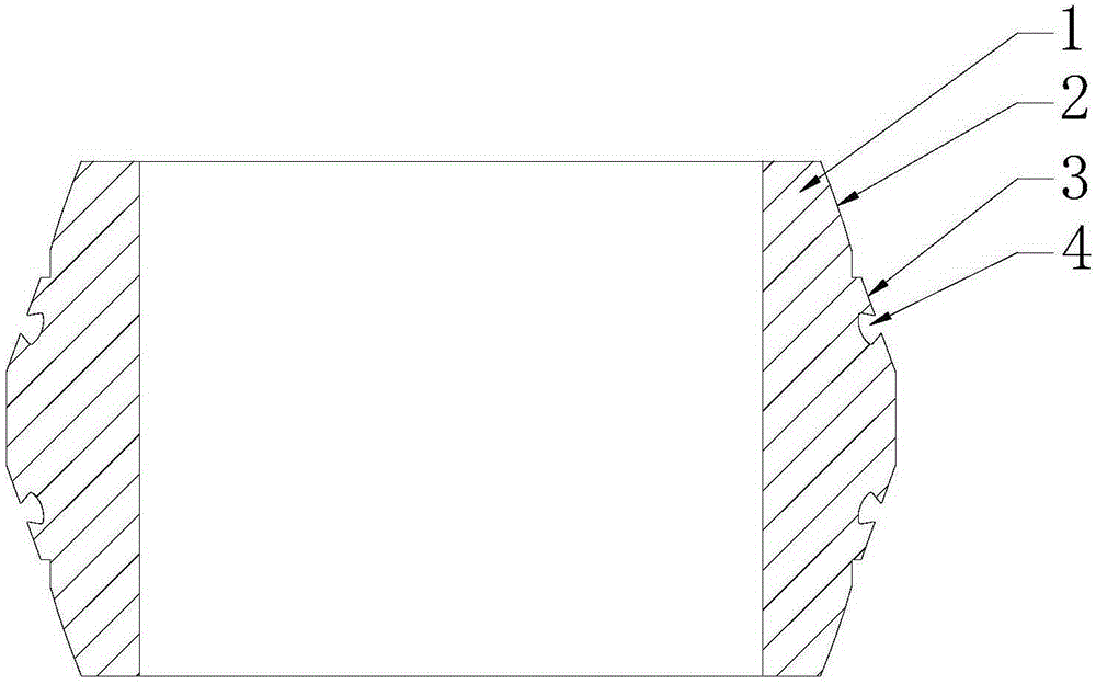
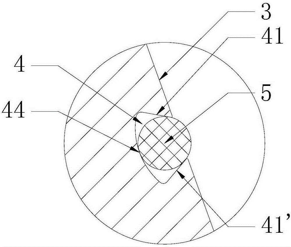
[0018] like figure 1 As shown, the present invention includes: a composite sealing ring 1 installed on the pipeline flange, a spherical sealing surface 2 arranged on the composite sealing ring 1, wherein the spherical sealing surface 2 is provided with a sealing slope 3, and the inside of the sealing slope 3 A non-standard sealing groove 4 is provided, and a second O-shaped sealing ring 5 is housed in the non-standard sealing groove 4 (such as image 3 shown).

[0019] The above-mentioned sealing slope 3 is a non-standard sealing surface.

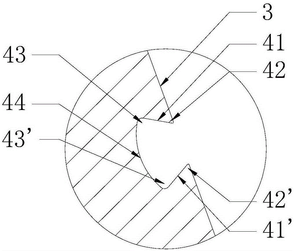
[0020] like figure 2 As shown, the inner cavity of the non-standard seal groove 4 is composed of the opposite non-standard seal groove side walls 41 and 41', and the non-standard seal groove notch rounded corners respectively arranged on the top of the non-standard seal groove side walls 41 and 41'. 42 and 42', the rounded corners 43 and 43' at the bottom of the non-standard sealing groove and the bottom 44 of the non-standard sealing g...


PUM


Abstract

An outer sealing groove structure of an O-shaped ring of a non-standard sealing face comprises a composite sealing ring installed on a pipeline flange, and a spherical sealing face arranged on the composite sealing ring. A sealing bevel is arranged on the spherical sealing face and is internally provided with a non-standard sealing groove. An O-shaped sealing ring is arranged in the non-standard sealing groove. The inner cavity of the non-standard sealing groove is in the shape of an inner dovetail groove structure installed in cooperation with the O-shaped sealing ring. By means of the outer sealing groove structure, it can be guaranteed that the O-shaped sealing ring and a sealing cone are sealed, the displacement problem of the O-shaped ring is solved during the installing and replacing process of the sealing ring, and sealing reliability is improved; and besides, deviation and sliding of the O-shaped ring are greatly reduced, the failure problem caused by interval meshing damage and extrusion of the O-shaped ring is solved, the service life of the O-shaped ring is greatly prolonged, and reliability of composite sealing is improved.

Description

technical field [0001] The invention relates to an underwater connector, in particular to an outer sealing groove structure of an O-ring on a non-standard sealing surface used in a composite internal and external pressure double seal in a deep water connector. It belongs to the field of offshore oil engineering. Background technique [0002] Since the deep-water connector must withstand the internal high-temperature and high-pressure oil and gas, it must also overcome the external low-temperature deep-water pressure. Therefore, for the sealing of the deep-water connector, a composite internal and external pressure double seal is often used. The internal O-ring is made of metal material. It is mainly used to seal the internal oil and gas pressure, not the O-ring of the non-standard sealing surface of metal materials. Because of its good corrosion resistance, it is mostly used to seal the external pressure of seawater. [0003] In order to install and fix the O-ring, it is ne...

Claims


Application Information

Patent Timeline
Patent Type & Authority Applications(China)
IPC IPC(8): F16L23/18
CPCF16L23/18
Inventor 李志刚王立权运飞宏曹为王宇臣曹永刘军王仁华徐祥娟何鑫
Owner CHINA NAT OFFSHORE OIL CORP
Learn More