Low-flow-resistance heat exchanger for natural circulation system

A circulating system and heat exchanger technology, applied in the direction of heat exchanger types, indirect heat exchangers, lighting and heating equipment, etc., can solve the problems of no gas remaining, the heat exchanger cannot be applied to the layout space, and the limited space, so as to reduce the The effect of flow resistance

Active Publication Date: 2016-01-06
CHINERGY CO LTD
View PDF8 Cites 1 Cited by
  • Summary
  • Abstract
  • Description
  • Claims
  • Application Information

AI Technical Summary

Problems solved by technology

[0005] In order to solve the problems that the current heat exchanger cannot be applied to the natural circulation system of nuclear energy, such as limited layout space, low flow resistance, and no gas remaining in the heat exchanger under natural circulation conditions, the patent of the present invention provides a heat exchanger suitable for the natural circulation system. Low flow resistance compact heat exchanger

Method used


Image

  • Low-flow-resistance heat exchanger for natural circulation system
  • Low-flow-resistance heat exchanger for natural circulation system
  • Low-flow-resistance heat exchanger for natural circulation system

Examples


Embodiment Construction

[0019] Below in conjunction with accompanying drawing and embodiment the patent of the present invention is further described. The following examples are used to illustrate the present invention, but are not intended to limit the scope of the present invention.

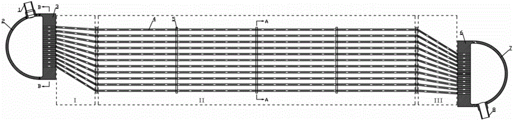
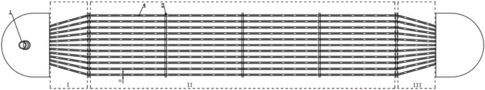
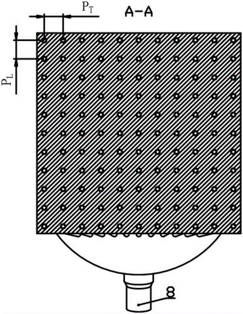
[0020] Fig. 1 is an assembly view of a heat exchanger according to an embodiment of the present invention. The heat exchanger in this embodiment includes: an inlet tube box 2 , an inlet tube plate 3 , a heat transfer tube bundle, an inlet support plate, an outlet support plate, an outlet tube plate 6 and an outlet tube box 7 . The heat transfer tube bundle extends continuously between the inlet tube sheet 3 and the outlet tube sheet 6 , and includes a plurality of heat transfer tubes 4 . In order to reduce flow resistance, in the heat exchanger of the present invention, the heat transfer tubes 4 in the heat transfer tube bundle use small diameter tubes (if no special instructions, the terms such as the pipe diameter ...


PUM


Abstract

The invention relates to a low-flow-resistance heat exchanger for a natural circulation system. The low-flow-resistance heat exchanger comprises an inlet tube box (2), an inlet tube plate (3), a heat transfer tube bundle, an inlet supporting plate, an outlet supporting plate, an outlet tube plate (6) and an outlet tube box (7). The heat transfer tube bundle is divided into an inlet shrinkage region, a heat exchange region and an outlet shrinkage region. The heat exchanger is a shell-free type heat exchanger. Small-diameter tubes are adopted as heat transfer tubes (4) in the heat transfer tube bundle. The inlet shrinkage region and the outlet shrinkage region of the heat transfer tube bundle incline downwards. The heat exchange region of the heat transfer tube bundle is horizontally arranged basically, no local high point or air accumulation is generated in the tube pass, low flow resistance is achieved, and the structure is compact.

Description

technical field [0001] The invention relates to the technical field of heat exchangers, in particular to a tubular heat exchanger with low flow resistance and compact structure used in natural circulation systems. Background technique [0002] Existing shell-and-tube heat exchangers are generally composed of heat transfer tubes, tube sheets, heads, shells, inlet and outlet nozzles, and the like. Heat transfer tubes are basic heat transfer elements that isolate hot and cold fluids and transfer heat. The tube sheet and head make the heat transfer tubes converge to the inlet and outlet nozzles, and the shell forms the shell-side pressure boundary. The hot and cold fluids flow and exchange heat on the tube and shell sides respectively. [0003] The heat transfer tubes of existing shell-and-tube heat exchangers generally adopt straight tubes or U-shaped tubes, and the spacing between tube bundles is the same as the spacing between tube plate holes. There are no special require...

Claims


Application Information

Patent Timeline
Patent Type & Authority Applications(China)
IPC IPC(8): F28D7/00
Inventor 吴莘馨李晓伟王晓欣宋宇
Owner CHINERGY CO LTD
Why Eureka
Try Eureka