Implementation method of PWM data transmission in input mode

A technology of input mode and data transmission, applied in the direction of electrical digital data processing, instruments, etc., can solve the problems of information loss, data loss, CPU reading data not fast enough, etc., to reduce the possibility of loss and ensure the effect of design

Inactive Publication Date: 2016-01-06
FUZHOU ROCKCHIP SEMICON
View PDF4 Cites 2 Cited by
  • Summary
  • Abstract
  • Description
  • Claims
  • Application Information

AI Technical Summary

Problems solved by technology

However, when the external input waveform changes rapidly, the traditional design method will cause the CPU to read the information of this register. This information may be overwritten by the subsequent waveform informati

Method used


Image

  • Implementation method of PWM data transmission in input mode
  • Implementation method of PWM data transmission in input mode

Examples


Example Embodiment

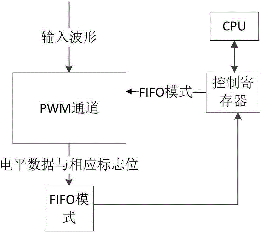
[0012] Such as figure 1 As shown, the implementation of the PWM in the input mode of the present invention transmits data. When the PWM is in the input mode, the CPU configures the input waveform to use the FIFO buffer mode in the control register. When the input waveform jumps, the jump information The corresponding flag bit is saved in the FIFO. When the stored value in the FIFO reaches the limit value, the CPU interrupts the PWM output waveform and reads the data in the FIFO; when the CPU finishes reading the data in the FIFO, it starts PWM output When the stored value in the FIFO reaches the limit value, the PWM generates an interrupt request signal. When the CPU detects the interrupt request signal, it interrupts the PWM output waveform. The transition information is the high and low level time of the external clock , The FIFO is the first-in first-out queue.

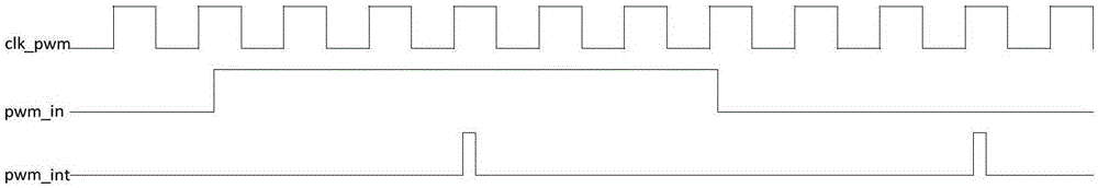
[0013] Such as figure 2 As shown, the input waveform is sampled, and if there is a high and low level flip, an in...


PUM


Abstract

The invention provides an implementation method of PWM data transmission in an input mode. According to the method, when a PWM is in the input mode, a CPU configures an input waveform to adopt an FIFO buffer mode in a control register; when the input waveform jumps, jump information and a corresponding zone bit thereof are stored into FIFO; when a storage value in the FIFO reaches a limit value, the CPU interrupts a PWM output waveform, and reads data in the FIFO; and after the CPU reads off the data in the FIFO, the PWM output waveform is started. The CPU does not need to frequently respond to the interruption, so that the data can be rapidly read; and the possibility of data loss is lowered.

Description

technical field [0001] The invention relates to a realization method of PWM transmitting data in an input mode. Background technique [0002] At present, in the input mode, the PWM will use the working clock to detect the jump of the external input waveform. When the external waveform jumps, the PWM will reflect the corresponding high-level time and low-level time to the register. (that is, the PWM records the time of the high and low levels of the external clock in the input mode, and the time information is recorded in this register through the PWM operation), and an interrupt is generated to notify the CPU to read the register. However, when the external input waveform changes rapidly, the traditional design method will cause the CPU to read the information of this register. This information may be overwritten by the subsequent waveform information, resulting in information loss. This data is the cycle of the waveform, the duration of the high and low levels and other re...

Claims


Application Information

Patent Timeline
IPC IPC(8): G06F13/24
Inventor 张明懿
Owner FUZHOU ROCKCHIP SEMICON
Why Eureka
Try Eureka