
Boost chip

A technology of boosting chip and boosting module, which is applied in the direction of instruments, adjusting electrical variables, output power conversion devices, etc., can solve the problem that the output voltage of the boosting chip cannot be adjusted to the target value, and the output accuracy of the front-stage chip is required to be high. problem, to avoid excessive output voltage accuracy and reduce costs

Active Publication Date: 2016-01-06
SHENZHEWN BAOLI MICROELECTRONICS CO LTD
View PDF6 Cites 5 Cited by
  • Summary
  • Abstract
  • Description
  • Claims
  • Application Information

AI Technical Summary

Problems solved by technology

[0003] The purpose of the present invention is to provide a boost chip, which aims to solve the problem in the prior art that the output voltage of the boost chip cannot be adjusted to the target value, which leads to high requirements on the output accuracy of the front-end chip.

Method used


Image

  • Boost chip
  • Boost chip
  • Boost chip

Examples


Embodiment Construction

[0030] In order to make the object, technical solution and advantages of the present invention clearer, the present invention will be further described in detail below in conjunction with the accompanying drawings and embodiments. It should be understood that the specific embodiments described here are only used to explain the present invention, not to limit the present invention.

[0031] In order to illustrate the technical solutions of the present invention, specific examples are used below to illustrate.

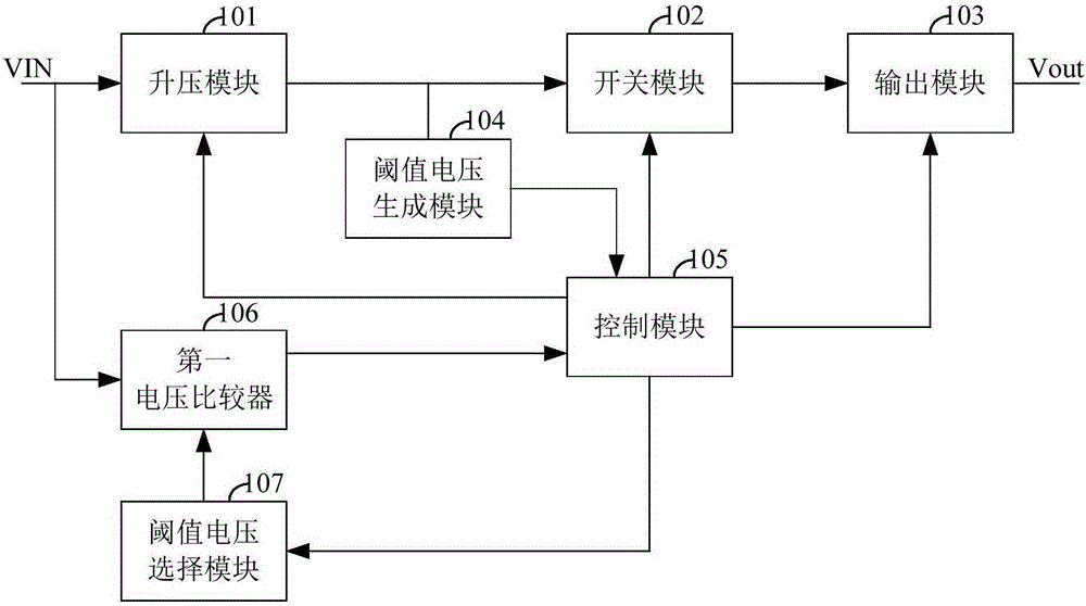
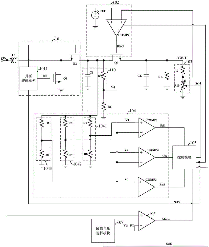
[0032] An embodiment of the present invention provides a boost chip, such as figure 1 As shown, the boost chip includes a boost module 101, a threshold voltage generation module 104, a switch module 102, an output module 103, a control module 105, a first voltage comparator 106, and a threshold voltage selection module 107;

[0033] The voltage input terminal of the boost module 101 is connected to the first input terminal of the first voltage comparator 106 to form an ...


PUM


Abstract

The invention relates to the technical field of charging and provides a boost chip. The boost chip comprises a boost module, a threshold voltage generation module, a switching module, an output module, a control module, a first voltage comparator and a threshold voltage selection module; when an input voltage is greater than a threshold voltage, the control module controls the boost module to output the input voltage to the switching module according to a comparison result, controls the switching module to be conducted so as to send the input voltage to the output module, and adjusts the output module so that the output module outputs a voltage same as the threshold voltage value according to the input voltage; and when the input voltage is smaller than the threshold voltage, the input voltage is boosted by controlling the boost module and then transmitted to the switching module according to the comparison result, the switching module is controlled to be conducted so that the boosted input voltage is transmitted to the output module, and the output module outputs the voltage. By comparing the input voltage with the threshold voltage, the input voltage is controlled to be boosted or bucked, and thus, the adjustment on the output voltage is achieved.

Description

technical field [0001] The invention relates to the technical field of charging, in particular to a voltage boosting chip. Background technique [0002] At present, most boost chips on the market do not have a step-down function. When the output voltage is lower than the input voltage, the output voltage cannot be adjusted to the target value. Higher output accuracy is required. To sum up, in the prior art, there is a problem that the output voltage of the boost chip cannot be adjusted to a target value, which leads to a high requirement on the output accuracy of the front-end chip. Contents of the invention [0003] The purpose of the present invention is to provide a boost chip, aiming to solve the problem in the prior art that the output voltage of the boost chip cannot be adjusted to the target value, which leads to high requirements on the output accuracy of the front-end chip. [0004] The present invention is achieved in this way. The first aspect provides a boost...

Claims


Application Information

Patent Timeline
Patent Type & Authority Applications(China)
IPC IPC(8): H02M3/156
Inventor 邓海飞耿翔
Owner SHENZHEWN BAOLI MICROELECTRONICS CO LTD
Learn More