Novel LED key light modulation technology

A button and dimming technology, which is applied in the field of new LED button dimming technology, can solve the problems of high cost and complex design, and achieve the effect of low cost and good substitution

Inactive Publication Date: 2016-01-06
CHONGQING ZEQINGJU SCI & TECH DEV
View PDF0 Cites 0 Cited by
  • Summary
  • Abstract
  • Description
  • Claims
  • Application Information

AI Technical Summary

Problems solved by technology

[0002] The existing LED button dimming technology mainly selects different lamp beads to emit light through the button distributor, and adjusts the brightness by emitting light from different numbers of lamp beads. This kind of LED button dimming technology has problems such as high cost and complicated design.

Method used


Image

  • Novel LED key light modulation technology

Examples


Embodiment Construction

[0008] The present invention will be further described below in conjunction with specific embodiments.

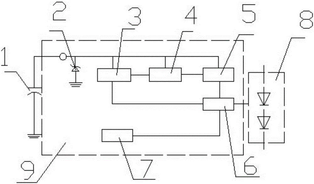
[0009] Such as figure 1 As shown, a new type of LED button dimming technology includes an integrated circuit with a clamping diode, an undervoltage protection module), an oscillator module, a delayer, a dimming control module, and a power-on reset module. , Connect bypass capacitors and LED modules outside the integrated circuit.

[0010] In the normal working state, this module does not work. The bypass capacitor voltage is clamped to a fixed voltage by the clamping diode. When the external switch enters the off state, the terminal voltage begins to drop, and when it drops to the undervoltage protection voltage threshold point , The under-voltage protection logic is reversed, the oscillator starts to work, the delayer starts timing, and the internal delay time is set to T. If the switch is turned on again in a short period of time (the time is less than the delay set time T),...


PUM


Abstract

Disclosed in the invention is a novel LED key light modulation technology comprising an integrated circuit. A clamping diode, an under-voltage protection module, an oscillator module, a time delay unit, a light modulation control module, and a power-on reset module are arranged inside the integrated circuit; and a bypass capacitor and an LED module group are connected outside the integrated circuit. The cost is low; and the light modulation technology can be integrated to the existing LED drive chip directly without any extra cost. The substitutability is high; a universal common switch on the existing market can be used as a light modulation key to realize the light modulation function.

Description

Technical field [0001] The present invention relates to LED button dimming technology, in particular to a novel LED button dimming technology. Background technique [0002] The existing LED button dimming technology mainly selects different lamp beads to emit light through the button distributor, and adjusts the brightness through different numbers of lamp beads. This kind of LED button dimming technology has problems such as high cost and complicated design. . Summary of the invention [0003] Aiming at the deficiencies in the prior art, the present invention provides a novel LED key dimming technology. [0004] The present invention is achieved through the following technical solutions: a new type of LED button dimming technology, including an integrated circuit, the integrated circuit is equipped with a clamping diode, undervoltage protection module), oscillator module, delayer, adjuster Optical control module, power-on reset module, bypass capacitor and LED module connected ou...

Claims


Application Information

Patent Timeline
Patent Type & Authority Applications(China)
IPC IPC(8): H05B37/02
Inventor 常小燕
Owner CHONGQING ZEQINGJU SCI & TECH DEV
Why Eureka
Try Eureka