In-flight refuelling device for electric storage system and aircraft equipped with such a device

A fuel supply and aircraft technology, applied to unmanned aircraft, aircraft, circuit devices, etc., can solve the problems that electric aircraft cannot reach the durability level, and achieve the effect of extending mission time

Inactive Publication Date: 2016-01-06
EURON AERONAUTIC DEFENCE & SPACE
View PDF8 Cites 16 Cited by
  • Summary
  • Abstract
  • Description
  • Claims
  • Application Information

AI Technical Summary

Problems solved by technology

[0004] The problem is that battery technology does not allow electric aircraft to achieve similar lev

Method used


Image

  • In-flight refuelling device for electric storage system and aircraft equipped with such a device
  • In-flight refuelling device for electric storage system and aircraft equipped with such a device
  • In-flight refuelling device for electric storage system and aircraft equipped with such a device

Examples


Embodiment Construction

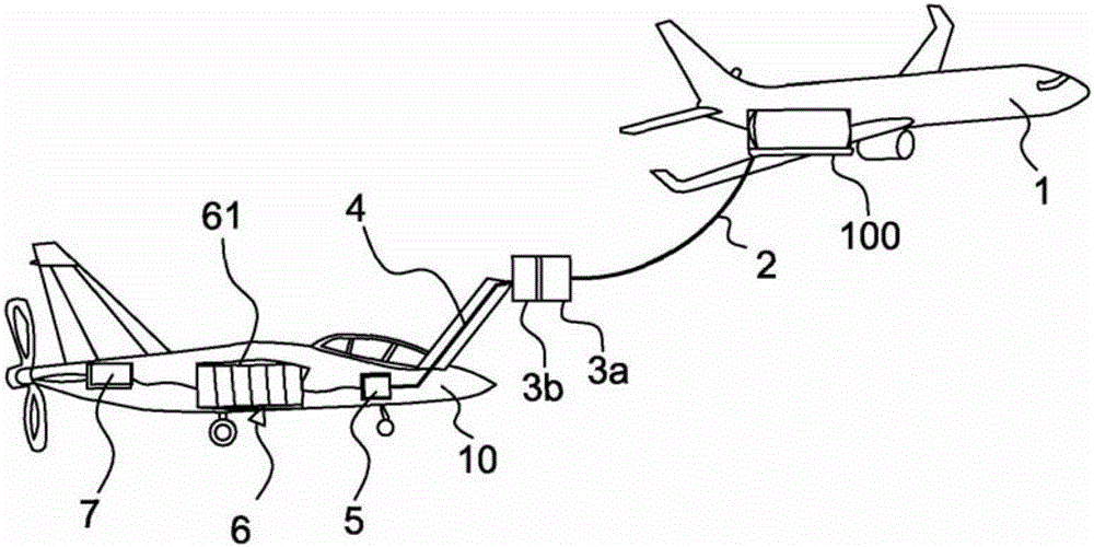
[0038] The invention proposes a system for recharging an on-board battery 6 in an electrically propelled aircraft 10 that can be recharged in flight.

[0039] figure 1 The system, schematically depicted in , comprises a charging aircraft 1, means 2, 3a, 3b, 4 for temporarily electrically connecting the charging aircraft to an electrically propelled aircraft that can be recharged in flight, and in the electrically propelled aircraft The charge adjustment device 5.

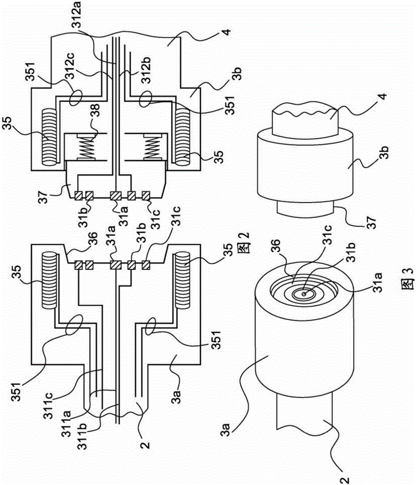
[0040] The temporary electrical connection means comprises according to an example a flexible electrical cable cable 2 towed by the charging aircraft, here a thrust reverser aircraft, a first connector element 3a at the end of this cable, a location where the battery is to be regenerated. The second connector element 3 b at the end of the bushing 4 of the charged aircraft 10 .

[0041] The cable may be a flexible cable placed upwind of the charging aircraft, and the cable may include, as in the prior art for refue...


PUM


Abstract

The subject of the invention is a system for recharging the batteries (6) carried on board an electrically powered aircraft (10), characterized in that it comprises a charging aircraft (1), means (2, 3a, 3b, 4) of temporarily electrically connecting the charging aircraft to the electrically powered aircraft and a charge-regulating device (5) in the electrically powered aircraft.

Description

technical field [0001] The invention relates to an in-flight refueling device for an electrically propelled aircraft comprising an on-board electrical storage system, an aircraft equipped with such a device, and a method for recharging a battery of an electrically propelled aircraft. The device provides for charging the aircraft, the aircraft that may be recharged, and the appropriate connection means. Background technique [0002] Since the introduction of lithium-based batteries on the market, there have been more and more demonstrations of aircraft or helicopters operating using the electrical energy stored electrochemically in the batteries. [0003] Obviously, the electric motors involved are very powerful and therefore require a very large input of on-board electrical energy. [0004] The problem is that, in the short or even medium term, battery technology does not allow electric aircraft to achieve similar levels of durability as their natural gas or kerosene-based ...

Claims


Application Information

Patent Timeline
IPC IPC(8): B64C39/02B64D27/24B64D39/00H01R13/62H01R24/38
CPCB64C39/024B64D27/24B64D39/00H01R13/6205H01R24/38B60L2200/10Y02T10/7072Y02T90/14B60L53/16Y02T50/60Y02T50/40Y02T10/70H01R13/629B64U50/34H02J7/0045H02J7/0014B64C39/02
Inventor 希琴姆·斯莫依查尔斯·内斯波卢斯布鲁诺·雷尚埃马纽埃尔·朱伯特迪迪埃·埃斯泰因
Owner EURON AERONAUTIC DEFENCE & SPACE
Why Eureka
Try Eureka