Head-wearing automatic cooling device and cooling method

An automatic cooling and head-mounted technology, which is applied in medical science, heating appliances for therapeutic treatment, cooling appliances for therapeutic treatment, etc., can solve problems such as inconvenient operation, high cost, and uncomfortable wearing

Active Publication Date: 2016-01-13
周榘
View PDF6 Cites 6 Cited by
  • Summary
  • Abstract
  • Description
  • Claims
  • Application Information

AI Technical Summary

Problems solved by technology

[0005] The technical problem to be solved by the present invention is to provide a head-mounted automatic cooling device and a cooling method, which can effectively solve the problems of slow coolin

Method used


Image

  • Head-wearing automatic cooling device and cooling method
  • Head-wearing automatic cooling device and cooling method
  • Head-wearing automatic cooling device and cooling method

Examples


Embodiment 1

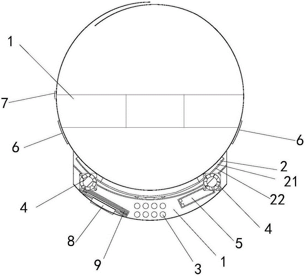
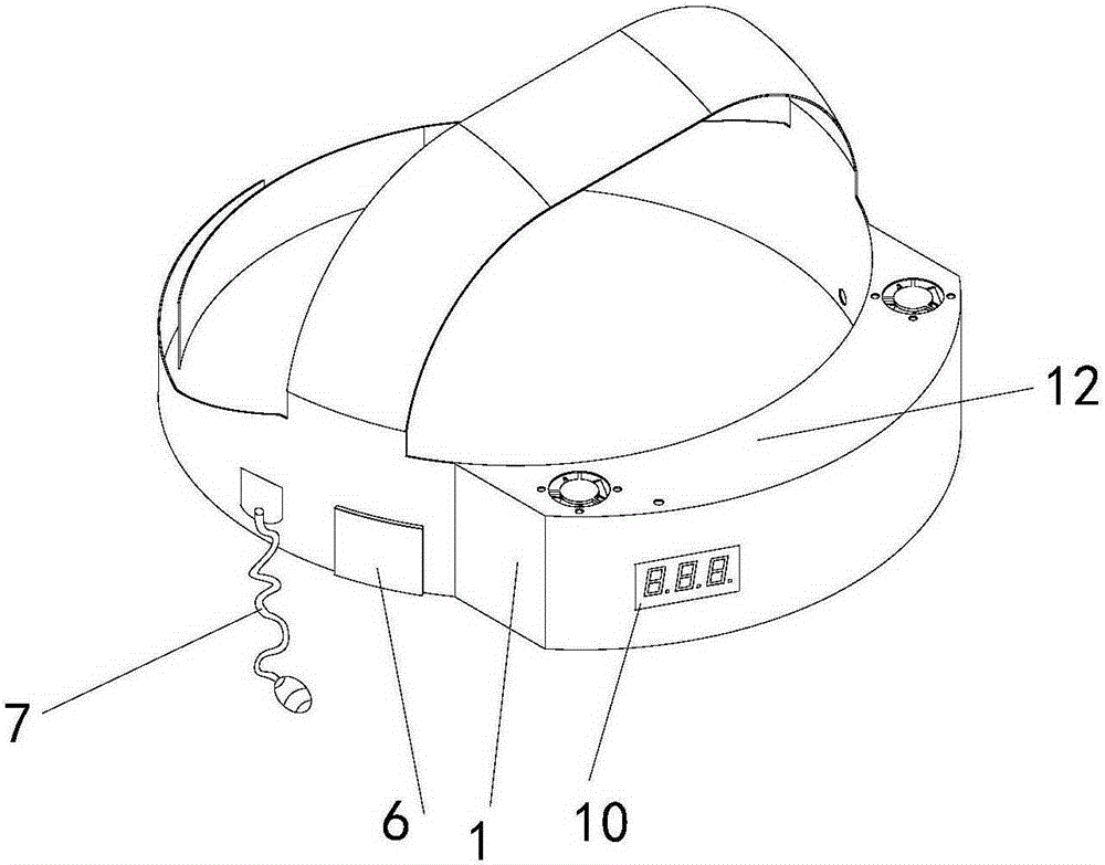
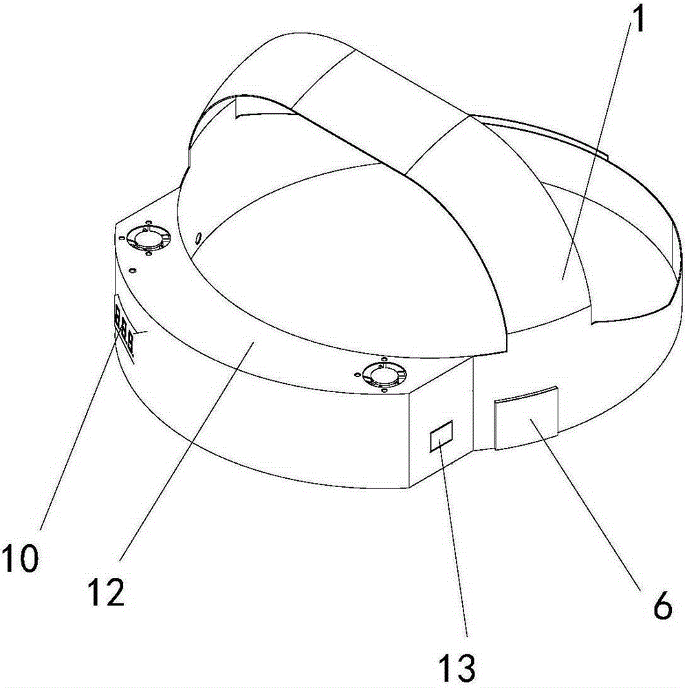
[0037] Embodiment 1. A head-mounted automatic cooling device. Combine below Figure 1 to Figure 4 The device provided in this embodiment will be described in detail.

[0038] see Figure 1 to Figure 5 The device provided in this embodiment includes a cooling headband 1, a cooling sticker 2, an air duct 3, a waterproof and silent fan 4, a rechargeable power supply 5, a head temperature sensor 6, an ear temperature sensor 7, and a central processing unit 8. The cooling sticker 2 is installed on the inner side of the cooling headband 1 surrounding the forehead part, and the inner side of the cooling patch 2 is exposed from the opening 11 of the cooling headband 1 around the inner side of the forehead part and contacts the skin. There are a plurality of circular hole-shaped vertical air ducts 3 in the middle of the forehead around the inner part of the band 1. The plurality of air ducts 3 are close to the outer surface of the cooling sticker 2 and pass through the cooling headba...

Embodiment 2

[0047] Embodiment 2, a head-mounted automatic cooling method. Combine below Figure 1 to Figure 5 The method provided in this embodiment will be described in detail.

[0048] see Figure 1 to Figure 6 , S201, switch on the rechargeable power supply 5, the head temperature sensor 6 and the ear temperature sensor 7 measure and monitor the head temperature and ear temperature respectively, and send the obtained head temperature signal and ear temperature signal to the central processing unit 8.

[0049] Specifically, after wearing the head-mounted automatic cooling device, the rechargeable power supply 5 is connected, and the rechargeable power supply 5 is the waterproof and silent fan 4, the head temperature sensor 6, the ear temperature sensor 7 and the central The processor 8 provides power, and the head temperature sensor 6 measures and monitors the head temperature at all times, and sends the obtained head temperature signal to the central processing unit 8; the ear tempe...


PUM


Abstract

The invention discloses a head-wearing automatic cooling device and a cooling method. The method comprises following steps: utilizing water-proof silent fans to control liquid volatilization in a cooling paste for fast cooling; utilizing head temperature sensors and an ear temperature sensor to measure and monitor head temperature and ear temperature at every moment and meanwhile sending signals of head temperature and ear temperature to a central processing unit; and determining whether body temperature is higher than date value for normal body temperature or not when the central processing unit receives signals of head temperature and ear temperature and obtains data of body temperature so as to further control the water-proof silent fans to start and stop. The head-wearing automatic cooling device and the cooling method have following beneficial effects: rapid cooling is achieved while body temperature can be monitored in a real-time manner and automatic cooling control is realized so that cooling degree is effectively controlled, excessive cooling is avoided and cooling speed is controllable; a patient's condition is conveniently mastered; and the head-wearing automatic cooling device is low in cost and long in acting time without too much manual intervention and is safe and convenient and is comfortable to wear without noise.

Description

technical field [0001] The invention relates to household and medical auxiliary equipment for cooling the human body, in particular to a head-mounted automatic cooling device and a cooling method. Background technique [0002] When the human body has a fever, the most dangerous thing is to injure the brain, and the brain needs to be cooled and protected as soon as possible. At present, there are two main physical methods for reducing fever and cooling in the human body: [0003] In the first way, volatile liquids such as water and alcohol are used to directly cool the human body surface skin through simple carriers (such as towels, gauze and children's ice patches, etc.). Its disadvantages are: slow cooling, short action time, poor effect, and uncontrollable cooling degree. [0004] The second way is to use special medical cooling blankets and cooling helmets, which generally use compressors or semiconductors as the cooling body. Its disadvantages are: high cost, inconven...

Claims


Application Information

Patent Timeline
IPC IPC(8): A61F7/02A61F7/00A61B5/01
Inventor 周榘
Owner 周榘
Why Eureka
Try Eureka