Kidney cooling capsule

A kidney and coolant technology, applied in the field of medical devices, can solve problems such as inability to cool the kidney, insert crushed ice, shorten operation time, etc., and achieve the effect of protecting kidney function

Inactive Publication Date: 2016-01-13
胡卫列 +1
View PDF5 Cites 5 Cited by
  • Summary
  • Abstract
  • Description
  • Claims
  • Application Information

AI Technical Summary

Problems solved by technology

However, there is a problem in the current laparoscopic implementation of this operation, that is, it is impossible to insert crushed ice through the puncture cannula, to cool the temporarily deprived kidney of blood supply, and to reduce the ambient temperature around the kidney, so that the kidney cannot be protected to the greatest extent. This disadvantage can only be offset by shortening the operation time through the proficiency of the operator

Method used


Image

  • Kidney cooling capsule
  • Kidney cooling capsule
  • Kidney cooling capsule

Examples


Embodiment 1

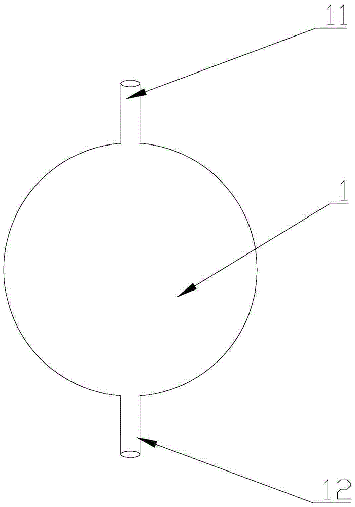
[0042] Coolant inlet 11 and coolant outlet 12 are respectively arranged on the upper and lower sides of the pouch 1. One way is that the coolant inlet 11 is connected with a low-temperature physiological saline bag. One way to extract the heat-exchanged physiological saline in the pouch 1 is to regularly inject and extract the physiological saline.

Embodiment 2

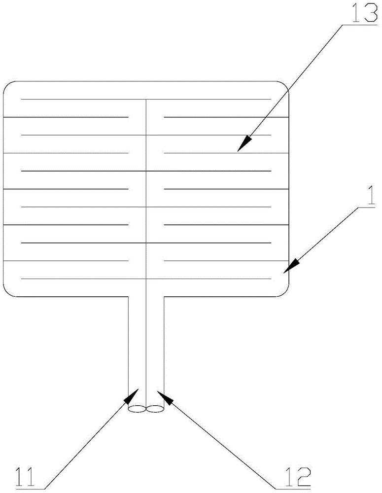
[0043] Preferred Embodiment 2 of the present invention: the cooling liquid inlet 11 and the cooling liquid outlet 12 are arranged side by side at the same position on the pouch 1 . The capsule bag 1 is provided with the capsule bag circulation circuit 13, and the capsule bag circulation circuit 13 has multiple setting modes, and a large circuit can be set, such as Figure 5 As shown, only a wall is bonded in the middle of the pouch, so that the cooling liquid detours from the lower part, and then flows out from the cooling liquid outlet 12. It is also possible to set up a long circuit. A low-temperature physiological saline bag is connected to the cooling liquid inlet 11, and the water pump 3 Pump the saline bag, the coolant outlet 12 can flow out directly for disposal, or return to the saline bag, the saline bag can be replaced with a new low-temperature saline bag according to needs, or ice cubes can be set around the saline bag for cooling .

Embodiment 3

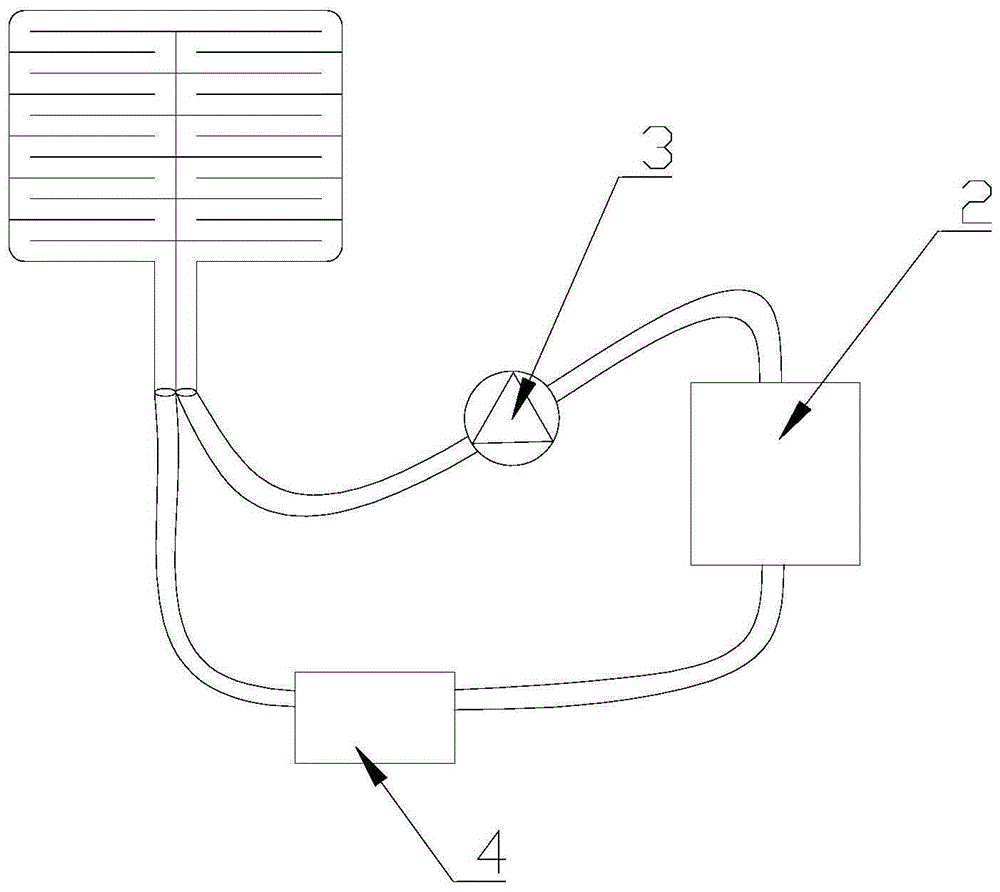
[0044] Preferred Embodiment 3 of the present invention: On the basis of Preferred Embodiment 2 of the present invention, a heat exchanger 4 is added, and the bladder 1, heat exchanger 4, cooling liquid container 2 and water pump 3 are formed into a circulation loop to further save manpower and material resources, without It is necessary to arrange personnel to pump regularly, and the equipment will automatically run and cool. The heat exchanger 4 can also be equipped with a temperature regulator and a temperature sensor to control the temperature within a constant range, and to cool the kidney at a constant temperature, which further protects the function of the kidney and is beneficial to the patient after surgery. recover.

[0045] This kidney cooling capsule can enter the body through the puncture hole of the laparoscope, and is placed around the operative field of the kidney, connected with ice-cold liquid. After the establishment of cold circulation, it can be wrapped or c...


PUM


Abstract

The invention discloses a kidney cooling capsule, comprising a capsule body for kidney cooling. The capsule may receive cooling liquid and is provided with a cooling liquid inlet and a cooling liquid outlet. The cooling liquid inlet of the kidney cooling capsule helps deliver the cooling liquid into the capsule body, and the cooling liquid is discharged through the cooling liquid outlet. During use, the kidney cooling capsule is entered as gauze into a body from a perforation sleeve of a laparoscope and is placed around a surgical field for the kidney, ice-cold cooling liquid is externally connected, and the bag body may enclose or cover the top and bottom of or partial surface of the kidney after being full so as to give the effect of broken ice application in approximately open operation conditions, cooling the kidney and effectively protecting the kidney function. The kidney cooling capsule is applicable to the field of medical instruments.

Description

technical field [0001] The invention relates to the field of medical equipment, in particular to a kidney cooling bag. Background technique [0002] At present, nephron-sparing surgery for renal tumors, that is, partial nephrectomy, is a common surgical method for early renal tumors. In the past, the operation was mostly open surgery. After the kidney and renal pedicle blood vessels were fully freed, a vascular clip was given to temporarily block the blood supply of the kidney, and immediately sprinkle crushed ice around the kidney to cool the kidney, thereby reducing the metabolism of the kidney. Protect the renal function, then enucleate the renal tumor, suture the incision of the kidney after the resection is completed, and finally loosen the blood vessel clamp to open the blood flow of the kidney. [0003] With the increasing popularity of ordinary laparoscopic techniques and even robotic-assisted laparoscopic surgery, kidney-sparing nephron surgery is mostly performed ...

Claims


Application Information

Patent Timeline
IPC IPC(8): A61F7/12
Inventor 胡卫列曾钦松
Owner 胡卫列
Why Eureka
Try Eureka