Glass crusher

A pulverizer and glass technology, applied in glass recycling, grain processing, recycling technology, etc., can solve the problem of long glass sheet jamming and other problems

Inactive Publication Date: 2016-01-13
深圳市光华中空玻璃工程有限公司
View PDF1 Cites 2 Cited by
  • Summary
  • Abstract
  • Description
  • Claims
  • Application Information

AI Technical Summary

Problems solved by technology

[0004] However, the above-mentioned patent has the following technical defects: due to the fast rotation of the roller shaft, long strips of glass that are not completely crushed are often thrown out; The glass sheet will fall directly to the downstream position of the working chamber under the action of gravity, that is, it will fall to the discharge port without further processing by the crushing hammer or fine crushing hammer. Such long glass sheets will cause jamming of subsequent conveying

Method used


Image

  • Glass crusher
  • Glass crusher
  • Glass crusher

Examples


Embodiment 1

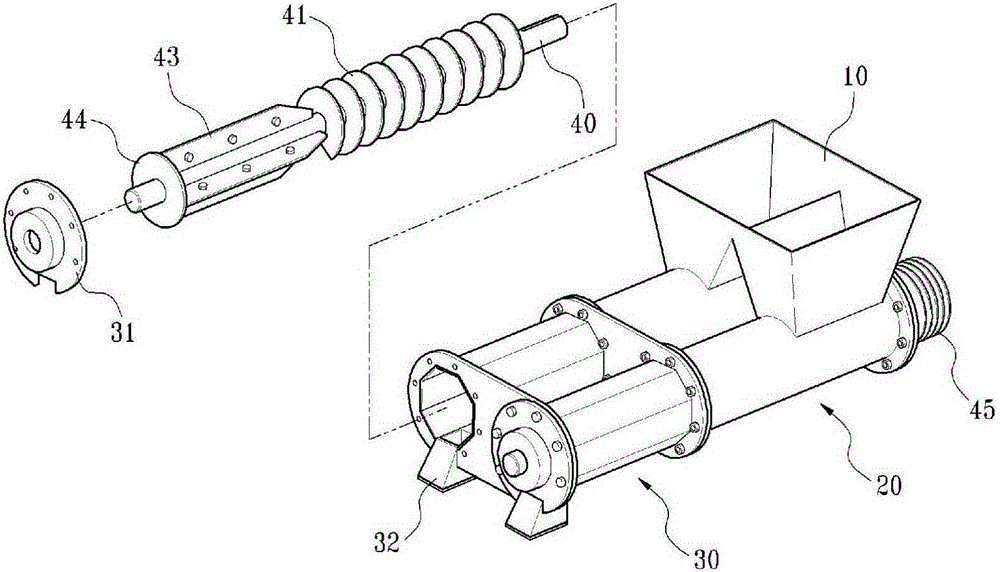
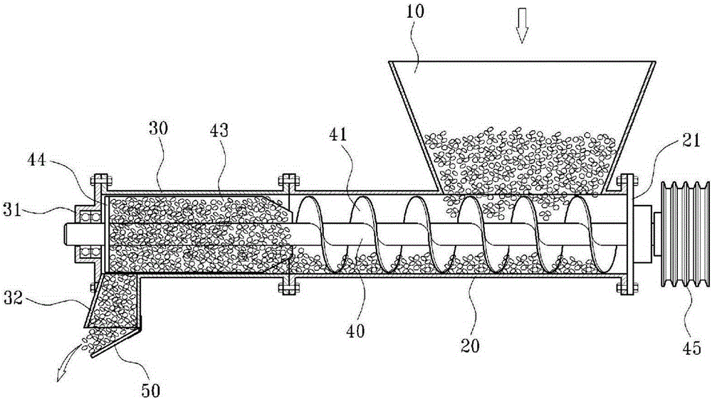
[0023] Such as figure 1 As shown, the glass pulverizer of this embodiment includes a housing, and is rotatably connected to two rotating shafts 40 inside the housing. 43. The housing includes two first cavities 20 for accommodating the auger knives 41 and two second cavities 30 for accommodating the stirring blades 43. The first cavity 20 is provided with a hopper 10, the second The second cavity 30 is provided with a discharge hopper 32 , and the inner cross section of the second cavity 30 is a regular hexagon corresponding to the number of the stirring blades 43 .

[0024] Such as figure 1 As shown, the first cavity 20 and the second cavity 30 are fixedly connected together through flanges, and the flanges at both ends of the second cavity 30 are connected as a whole. The input hoppers 10 on the two second cavities 30 are connected as a whole, and the output hoppers 32 on the two first cavities 20 are arranged at intervals. Such as figure 1 , 2 As shown, an airbag 45 fo...

Embodiment 2

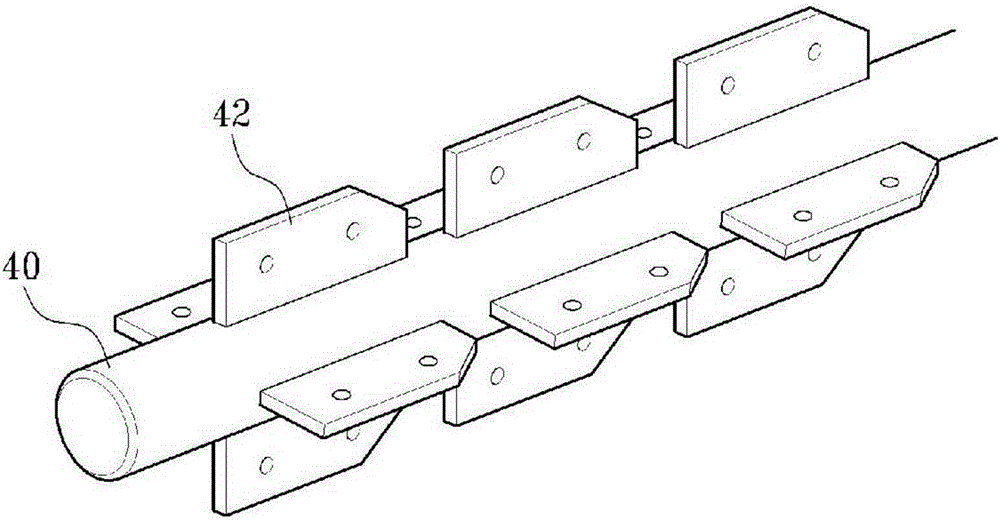
[0028] Such as image 3 As shown, the difference between this embodiment and the first embodiment is that there are four long-axis blades consistent with the length direction of the rotating shaft 40 , but each long-axis blade is divided into three stirring blocks 42 . Along the length direction of the rotating shaft 40, the distance between adjacent stirring blocks 42 is 2-3 cm.

Embodiment 3

[0030] Such as Figure 4 As shown, the difference between this embodiment and Embodiment 1 is that there are two arc-shaped blades 24 that are consistent with the central axis of the rotating shaft 40 (the one at the bottom, in the Figure 4 not visible in ).


PUM


Abstract

The invention discloses a glass producing device and particularly relates to a glass crusher. The glass crusher comprises a shell and a rotating shaft rotationally connected into the shell. The rotating shaft is provided with spiral auger knifes and stirring blades. The shell comprises first cavities for containing the spiral auger knifes and second cavities for containing the stirring blades. The first cavities are provided with feeding hoppers. The second cavities are provided with discharging hoppers. The inner section of the second cavities is a regular hexagon and the second cavities correspond to the stirring blades in number. By means of the glass crusher, the technical defect that in the prior art, strip-shaped glass sheets exist and block follow-up conveying is overcome, glass can be broken completely, and strip-shaped glass sheets are prevented.

Description

technical field [0001] The invention relates to glass production and processing equipment, in particular to a glass pulverizer. Background technique [0002] In the flat glass process, after the raw material ratio, melting, forming, annealing, cutting, sheet taking, packaging and other processes, the flat glass plate is finally produced. In the cutting process, the glass must go through processes such as cross-cutting, longitudinal cutting, transverse breaking, and longitudinal edge breaking before it can be cut into flat glass plates. In the longitudinal edge breaking, the edge of the flat glass plate needs to be broken off, and the broken glass falls on the glass hopper below and is crushed. Conveyed by multi-stage belt conveyor, it is sent back to the cullet warehouse of the raw material workshop, and then re-mixed into the raw material for reuse. [0003] Most of the existing pulverizers use the shaft to drive the pulverizing hammer to pulverize the glass, such as the ...

Claims


Application Information

Patent Timeline
Patent Type & Authority Applications(China)
IPC IPC(8): B02C19/22B02C19/00
CPCY02W30/60
Inventor 冯云鹏
Owner 深圳市光华中空玻璃工程有限公司
Why Eureka
Try Eureka