Wooden door paint spraying clamping device

A technology of clamping device and wooden door, which is applied in the field of devices supporting workpieces, can solve the problems of long time consumption and low work efficiency, and achieve the effect of short time consumption, ensuring stability and good self-locking effect

Inactive Publication Date: 2016-01-13
CHONGQING YISHI TIANRUN SUIT DOOR
View PDF0 Cites 23 Cited by
  • Summary
  • Abstract
  • Description
  • Claims
  • Application Information

AI Technical Summary

Problems solved by technology

Some small wooden door factories mostly use the method of manual spray painting, that is, first fix the wooden board and spray one side, and then turn over and spray the other side after the sprayed side is completely dry, and then proceed to the next process after the other side is completely dry , time-consuming and low work efficiency

Method used


Image

  • Wooden door paint spraying clamping device
  • Wooden door paint spraying clamping device
  • Wooden door paint spraying clamping device

Examples


Embodiment 1

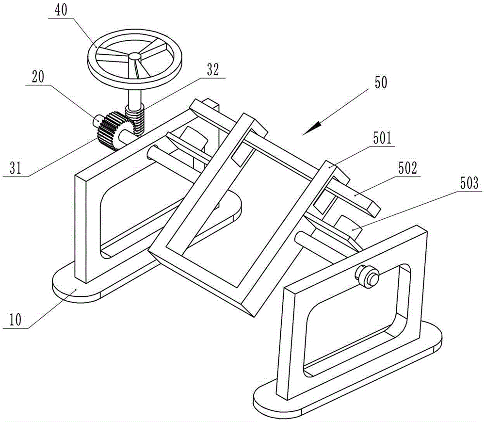
[0022] like figure 1 As shown, the wooden door spraying clamping device includes a frame 10, a rotating rod 20, a worm wheel 31, a worm 32, a rotating handle and a clamping unit for clamping a wooden board. The clamping unit is rotatably installed on the frame 10 through the rotating rod 20 , and the worm wheel 31 and the rotating rod 20 are coaxially welded and fixed together. The worm screw 32 is engaged with the worm wheel 31, and the turning handle is welded on the worm screw 32. The clamping unit includes a clamping frame 501 , a clamping rod 502 and an electromagnet 503 . The clamping frame 501 is U-shaped, and the two side walls of the clamping frame 501 are processed with slide grooves, and the clamping rod 502 can slide up and down in the slide grooves. The clamping rod 502 is made of iron, and the outer wall of the clamping rod 502 is coated with antirust paint. When the electromagnet 503 is energized, the electromagnet 503 and the clamping rod 502 attract magneti...

Embodiment 2

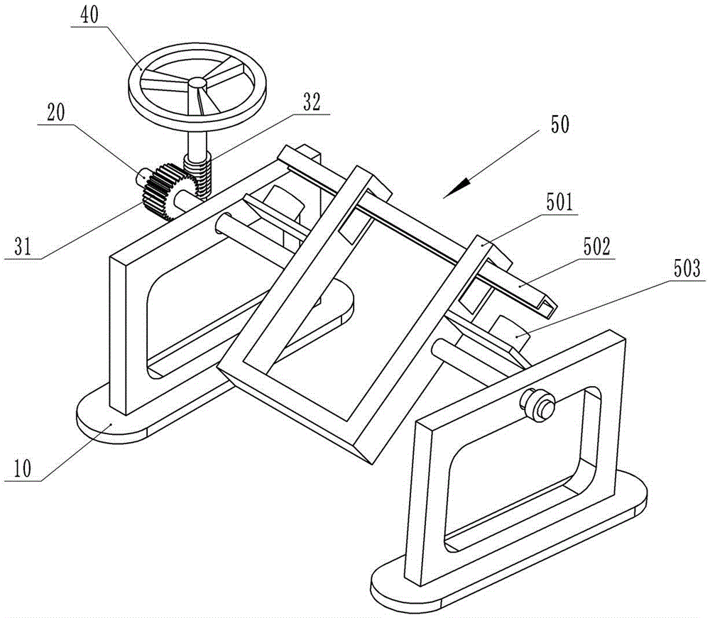
[0025] like figure 2 As shown, the difference between this embodiment and Embodiment 1 is that the clamping rod 502 is provided with a groove for accommodating part of the wood board. The planks can be snapped into the grooves for better clamping. Moreover, the inner wall of the groove is covered with a layer of rubber layer. When the clamping rod 502 clamps the board, it has a relatively high speed, and the rubber layer has a certain buffering effect to avoid damage to the board due to the fast speed.

Embodiment 3

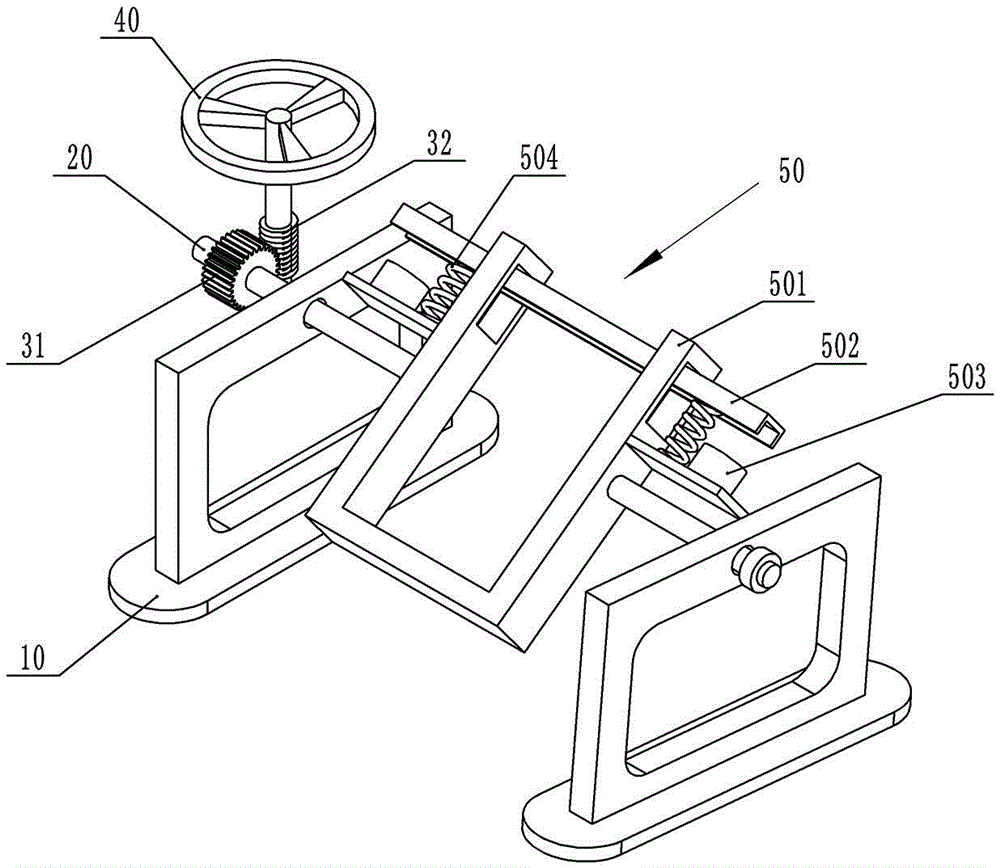
[0027] like image 3 , Figure 4 As shown, the difference between this embodiment and Embodiment 2 is that this solution also includes an elastic member 504 for the reset member of the clamping rod 502 . The elastic member 504 is a stainless steel compression spring, the upper end of the elastic member 504 is fixed on the clamping rod 502 , and the lower end is fixed on the clamping frame 501 . When the electromagnet 503 is energized, the electromagnet 503 and the clamping rod 502 are magnetically attracted to each other, and overcome the elasticity of the elastic member 504 to clamp the plank; when the electromagnet 503 is powered off, the elastic member 504 automatically ejects the clamping rod 502 , without manually removing the clamping rod 502.


PUM


Abstract

The invention belongs to the field of workpiece supporting devices, and particularly discloses a wooden door paint spraying clamping device. The wooden door paint spraying clamping device comprises a rack, a rotation rod, a worm gear, a worm, a rotation handle and a clamping unit used for clamping a wooden plate. The clamping unit is rotationally arranged on the rack through the rotation rod. The worm gear and the rotation rod are coaxially fixed. The worm is engaged with the worm gear. The rotation handle is fixed to the worm. The worm gear and the worm have a good self-locking function. Once the worm stops rotating, the worm gear cannot automatically rotate, and fixing stability is ensured. The overturning of the wooden plate can be achieved by rotating the worm, and operation is convenient and fast. Compared with a traditional spraying manner, according to the scheme, after one face of the wooden plate is sprayed, the wooden plate is immediately overturned, the other face of the wooden plate is sprayed, drying of paint does not need be waited, the consumed time is short, and the work efficiency is improved.

Description

technical field [0001] The invention belongs to the field of devices for supporting workpieces, in particular to a wooden door spraying and clamping device. Background technique [0002] Suit doors generally refer to composite doors that use solid wood as the main material, MDF on the outside as the balance layer, domestic or imported natural veneer as the veneer, made after high-temperature hot pressing, and sprayed with high-grade environmental protection wood paint on the outside. , in short, from the inside to the outside, it is required to be wood. The conventional wooden door manufacturing process is: blanking→cutting→rough grinding→press forming→edge trimming→milling→printing→hand-applied skin→punching→trial fitting→finishing→painting→packing and storage. Painting is one of the important processes in wooden door making. Some small wooden door factories mostly use the method of manual spray painting, that is, first fix the wooden board and spray one side, and then tu...

Claims


Application Information

Patent Timeline
Patent Type & Authority Applications(China)
IPC IPC(8): B05B13/02B05B15/00
CPCB05B13/02B05B13/0221B05B13/0278B05B15/00
Inventor 任英
Owner CHONGQING YISHI TIANRUN SUIT DOOR
Why Eureka
Try Eureka