
Automatic paint spraying device for plate processing

A technology for sheet metal processing and sheet metal processing, applied in the field of automatic painting devices for sheet metal processing, can solve the problem of low degree of automation, and achieve the effects of speeding up drying speed, convenient painting and high degree of automation

Inactive Publication Date: 2020-08-21
SUZHOU ODIHUA ELECTRONIC CO LTD
View PDF1 Cites 5 Cited by
  • Summary
  • Abstract
  • Description
  • Claims
  • Application Information

AI Technical Summary

Problems solved by technology

[0003] However, the above-mentioned technical solution still has the following disadvantages in actual use: only one side of the board can be painted, and when the other side of the board needs to be painted, manual flipping is required, and the degree of automation is not high.

Method used


Image

  • Automatic paint spraying device for plate processing
  • Automatic paint spraying device for plate processing
  • Automatic paint spraying device for plate processing

Examples


Embodiment 1

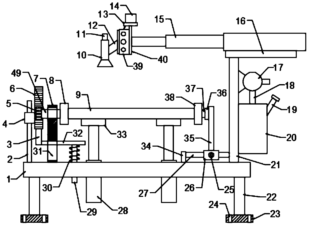
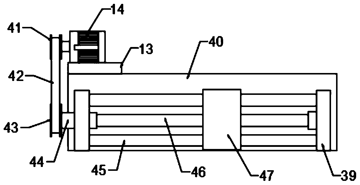
[0028] see Figure 1-3 , in an embodiment of the present invention, an automatic painting device for plate processing, including a workbench 1, a plate 9 and a paint spray head 10, a third vertical plate 21 is fixed on the workbench 1, and a paint bucket is installed on the third vertical plate 21 20, the paint bucket 20 is provided with a filling pipe 19; the second electric telescopic rod 28 and the first vertical plate 7 are installed on the workbench 1, and the telescopic end of the second electric telescopic rod 28 is connected with a support plate 33, the first A bearing on the vertical plate 7 is connected with a first rotating shaft 49, and one end of the first rotating shaft 49 is provided with a first splint 8, and the workbench 1 is also provided with a clamping assembly for clamping the plate 9;

[0029] The top of the third vertical plate 21 is provided with a mount 16, the mount 16 is equipped with a first electric telescopic rod 15, the telescopic end of the fir...

Embodiment 2

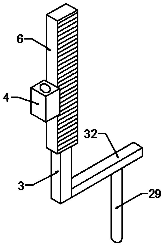
[0040] see Figure 4 , in the embodiment of the present invention, an automatic painting device for plate processing is different from embodiment 1 in that a baking lamp 48 is installed on the workbench 1; after one side of the plate 9 is painted, turn it over to the lower side, The baking lamp 48 can dry the paint to speed up the drying speed; after the painting on the other side is completed, the second electric telescopic rod 28 drives the support plate 33 to rise, and the support plate 33 no longer presses the cross bar 32, and is driven by the compressed spring 30 The cross bar 32 moves up, and the rack 6 is used to drive the plate 9 to turn over again, and the other side of the plate 9 can be dried by the oven lamp 48 .


PUM


Abstract

The invention is suitable for the technical field of automation equipment and provides an automatic paint spraying device for plate processing. The automatic paint spraying device comprises a workingtable, a plate and a paint sprayer; a second electric telescopic rod and a first vertical plate are mounted on the working table; a bracing plate is connected with the telescopic end of the second electric telescopic rod; a first rotary shaft is connected with the first vertical plate through a bearing; a first clamping plate is arranged at one end of the first rotary shaft; a clamping component is further arranged on the working table; a riser is connected with the telescopic end of a first electric telescopic rod; a moving component is arranged on the riser; and an overturning component is further arranged on the working table. According to the automatic paint spraying device, the second electric telescopic rod drives the bracing plate to descend, the bracing plate presses a transverse rod downwards to drive the transverse rod and a rack to move downwards as a whole, so that a gear is driven to rotate; the first clamping plate and a second clamping plate drives the plate to overturn,and then, the paint sprayer sprays paint to the plate; and the automatic paint spraying device can spray paint to two surfaces of the plate and is high in degree of automation.

Description

technical field [0001] The invention belongs to the technical field of automation equipment, in particular to an automatic painting device for plate processing. Background technique [0002] In the Chinese patent with the authorized announcement number CN207981527U, a panel paint spraying device for furniture production is disclosed, including a paint spraying workbench. One side of the table is equipped with a paint brushing support frame, the discharge end of the plate conveying device is connected with a paint drying box, and the plate conveying device is interspersed and arranged on both sides of the paint drying box. The paint on the plate can be evenly spread through the brush plate and bristles, so that the spraying effect is better. At the same time, the cylinder barrel and piston rod can automatically adjust the height of the brush plate, which can be adjusted according to different thickness of the plate. [0003] However, the above-mentioned technical solution st...

Claims


Application Information

Patent Timeline
Patent Type & Authority Applications(China)
IPC IPC(8): B05B16/20B05B13/02B05B13/04B05D3/02
CPCB05B13/0228B05B13/0271B05B13/0285B05B13/041B05B16/20B05D3/0254
Inventor 史骅婷
Owner SUZHOU ODIHUA ELECTRONIC CO LTD
Learn More