
Efficient paper cutter

A paper cutter, high-efficiency technology, applied in the direction of metal processing, etc., can solve the problems of not being able to use the demand to adjust the cutting, not meeting the use demand, single function, etc., to achieve the effect of improving paper cutting efficiency, convenient operation, and easy adjustment

Inactive Publication Date: 2016-01-13
CHANGZHOU SINAJET SCI & TECH
View PDF4 Cites 0 Cited by
  • Summary
  • Abstract
  • Description
  • Claims
  • Application Information

AI Technical Summary

Problems solved by technology

The existing paper cutter has a fixed structure and a single function. The paper cutter is fixed on one side of the bottom plate, and the cutting cannot be adjusted according to the usage requirements, which cannot meet the growing usage requirements.

Method used


Image

  • Efficient paper cutter

Examples


Embodiment Construction

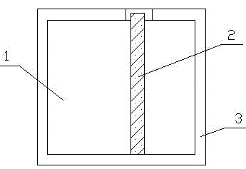
[0009] Such as figure 1 It is a structural schematic diagram of the present invention, a high-efficiency paper cutter, including a base plate 1 and a paper cutter 2, a chute 3 is arranged around the base plate 1, and the paper cutter 2 is arranged in the chute 3. During use, the fixed block at one end of the paper cutter 2 is embedded in the chute 3 and can move in the chute 3 .

[0010] The above description is only illustrative of the present invention, rather than restrictive. Those of ordinary skill in the art understand that many modifications, changes or the like can be made without departing from the spirit and scope defined by the appended claims. effect, but all will fall within the protection scope of the present invention.


PUM


Abstract

The invention relates to the technical field of cutting equipment, in particular to an efficient paper cutter. The efficient paper cutter comprises a base plate and paper cutter bodies, sliding grooves are formed in the periphery of the base plate, and the paper cutter bodies are arranged in the sliding grooves. The efficient paper cutter is simple in structure and convenient to operate; easy adjustment of the paper cutter bodies is achieved, various different paper cutting requirements are met, and the paper cutting efficiency is effectively improved.

Description

technical field [0001] The invention relates to the technical field of cutting equipment, in particular to a high-efficiency paper cutter. Background technique [0002] The paper cutter is a traditional product, which is used to deal with the paper cutting needs in the later stage of printing. The existing paper cutter has a fixed structure and a single function, and the paper cutter is fixedly arranged on one side of the bottom plate, and the cutting cannot be adjusted according to the usage requirements, which cannot meet the increasing usage requirements. Contents of the invention [0003] In order to overcome the existing above-mentioned shortcomings, the present invention provides a high-efficiency paper cutter. [0004] The technical solution adopted by the present invention to solve the technical problem is: a high-efficiency paper cutter, including a bottom plate and a paper cutter, a chute is arranged around the bottom plate, and the paper cutter is arranged in t...

Claims


Application Information

Patent Timeline
Patent Type & Authority Applications(China)
IPC IPC(8): B26D7/26
Inventor 陈文军
Owner CHANGZHOU SINAJET SCI & TECH
Learn More