
An aircraft flame guiding structure

A technology of aircraft and tail flame, which is applied in the field of thermal protection of aerospace vehicles

Active Publication Date: 2017-05-31
CHINA ACAD OF LAUNCH VEHICLE TECH
View PDF7 Cites 0 Cited by
  • Summary
  • Abstract
  • Description
  • Claims
  • Application Information

AI Technical Summary

Problems solved by technology

[0003] The technical solution problem of the present invention is: overcome the deficiencies in the prior art, propose a kind of aircraft flame guiding structure, solve the thermal protection problem of engine tail nozzle and the thermal protection problem of the joint of flame guiding device and the thermal protection problem of tail end face, ensure that the aircraft is flying During the process, the tail nozzle, the flame guide device and the tail end surface can meet the normal use requirements

Method used


Image

  • An aircraft flame guiding structure
  • An aircraft flame guiding structure
  • An aircraft flame guiding structure

Examples


Embodiment Construction

[0015] There are steps in the new high-efficiency engine tail nozzle used by aerospace vehicles, which lead to high pressure and high heat flow at both ends. The pressure and heat flow in the middle section are stable in the longitudinal area, and the highest heat flow is 3600kW / m2. According to the analysis of the flow structure, there are different degrees of compression in the channel. , expansion, separation and other flow structures, resulting in the phenomenon of high pressure / high heat flow alternately. In order to prevent the tail flame ejected from the tail nozzle from burning the rear of the fuselage, a corresponding flame guide structure is designed.

[0016] The present invention mainly considers a flame guiding structure of this type of aircraft tail nozzle. The flame-guiding structure has the function of diverting the hot air flow of the engine tail nozzle to conduct flame-guiding, so it is necessary to design the connecting parts and their heat sealing. Conside...


PUM


Abstract

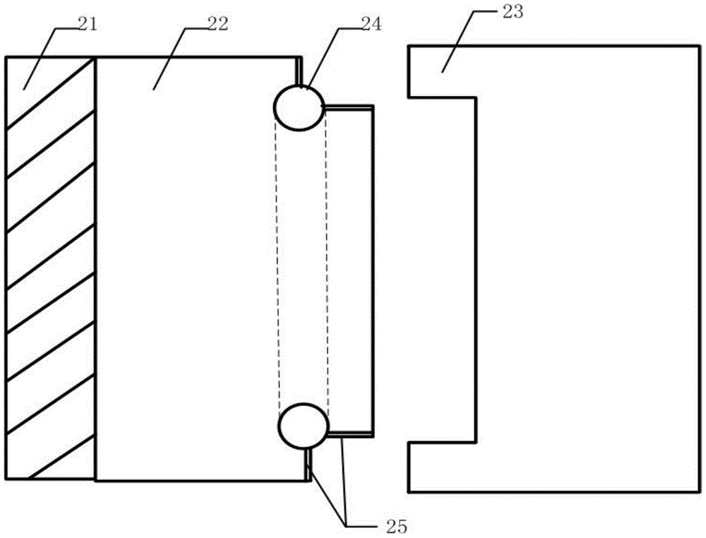
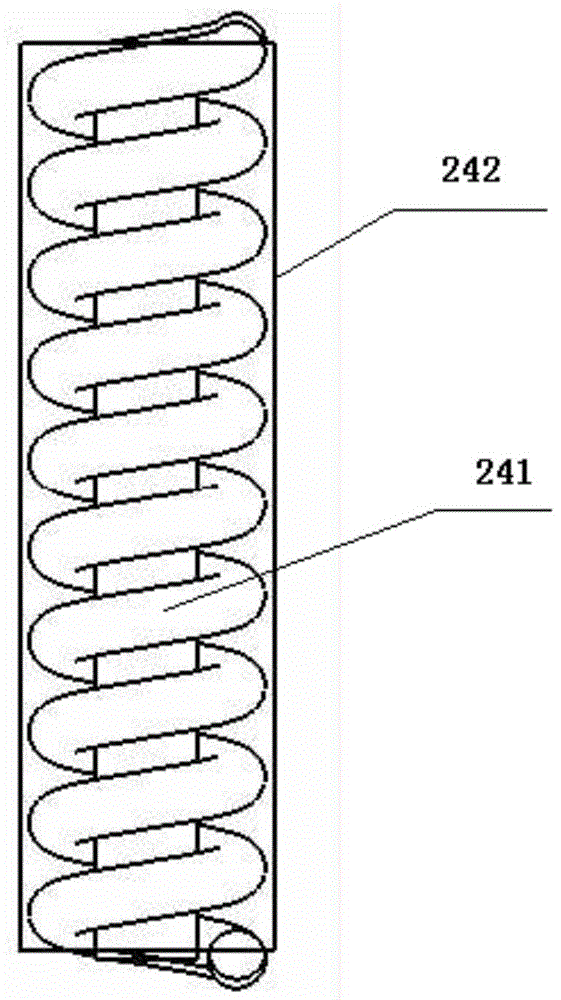
The invention relates to a flame piloting structure for an aircraft. The structure is positioned behind an air inlet exhaust nozzle of an engine; a transitional section exists behind the air inlet exhaust nozzle of the engine; and the transitional section is used for connecting the flame piloting structure and an aircraft body. The transitional section comprises a first connecting piece and a second connecting piece; the space between the first connecting piece and the aircraft body is filled with a piece of high-temperature-resistant heat insulating felt; a groove is formed in the jointed part of the first connecting piece and the second connecting piece; a sealing piece is placed in the groove; the sealing piece comprises high-temperature cotton, a flexible spring and a ceramic fiber cloth from inside to outside, wherein the flexible spring is made of high-temperature metal; the ceramic fiber cloth coats the flexible spring; the space between the sealing piece and the groove is filled with a sealing adhesive; one layer of ceramic fiber cloth is also arranged between the first connecting piece and the second connecting piece; the second connecting piece is connected with a flame piloting groove; the flame piloting groove is made of a high-temperature-resistant C / C composite material; a shunting structure is arranged in the flame piloting groove; and tail flame ejected by the engine passes through the transitional section along an air inlet and is shunted by the shunting structure in the flame piloting groove to be ejected out from the two sides of the exterior of the flame piloting groove.

Description

technical field [0001] The invention provides an aircraft flame guiding structure, which belongs to the thermal protection technology of aerospace vehicles. Background technique [0002] In order to achieve high-efficiency flight, the new engine used by the aerospace vehicle needs to eject the tail flame generated by it out of the body through the tail nozzle. Due to the characteristics of high temperature, high pressure and high enthalpy, the tail flame can burn the aircraft structure behind the tail nozzle in a short time when it is ejected. In order to solve the above problems, it is necessary to design a flame guide structure that can be connected to the airframe. When the above conditions are met, exhaust the tail flame from the side of the fuselage without affecting the structure of the rear of the fuselage. At present, the engine used by this type of aerospace vehicle has little relevant news in the world, and the design of the guide flame structure of the tail nozzl...

Claims


Application Information

Patent Timeline
Patent Type & Authority Patents(China)
IPC IPC(8): B64G1/58B64C1/40
Inventor 卢琦费王华申亮钟杰华娄依志惠俊鹏马梦颖杨旸张雯毕永涛潘健
Owner CHINA ACAD OF LAUNCH VEHICLE TECH
Learn More