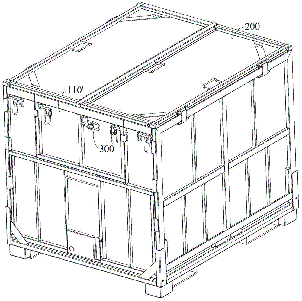
Lock and tray box

A pallet box and lock technology, which is applied in the direction of locking equipment, rigid containers, containers, etc., can solve problems such as damage to the side wall parts of the hook lock handle, and achieve the effects of low cost, convenient operation and simple lock structure.

Active Publication Date: 2016-01-13
CHINA INTERNATIONAL MARINE CONTAINERS (GROUP) CO LTD +2
View PDF5 Cites 11 Cited by
  • Summary
  • Abstract
  • Description
  • Claims
  • Application Information

AI Technical Summary

Problems solved by technology

In actual operation, the hook lock handle is easy to turn over and ride on the lock bracket 310 (see Image 6 ), or, the hook lock handle is not pressed into the limiting space S, but is supported by the limiting part 320 (see Figure 7 ), these two cases will cause the hook lock 300

Method used


Image

  • Lock and tray box
  • Lock and tray box
  • Lock and tray box

Examples


no. 1 example

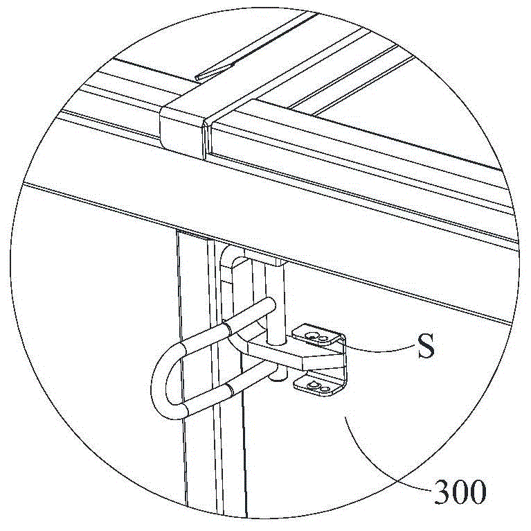
[0048] refer to Figure 9-Figure 11, the lock 10 of the present embodiment comprises a lock plate 11, a pin shaft 12 and an elastic member 14. The upper end of the lock plate 11 has a hook portion 111, and a perforation 112 is provided below the hook portion 111, and one end of the pin shaft 12 passes through the perforation 112 and is fixed. on the end wall 100. The elastic member 14 is sleeved on the outer periphery of the pin shaft 12 and pressed on the locking plate 11 . The lock plate 11 rotates around the pin shaft 12 to be in Figure 10 Locked state as shown or Figure 18 In the open state shown, in the locked state, the hook portion 111 is locked with the top cover 200; The lock plate 11 is held in a locked state or an open state.

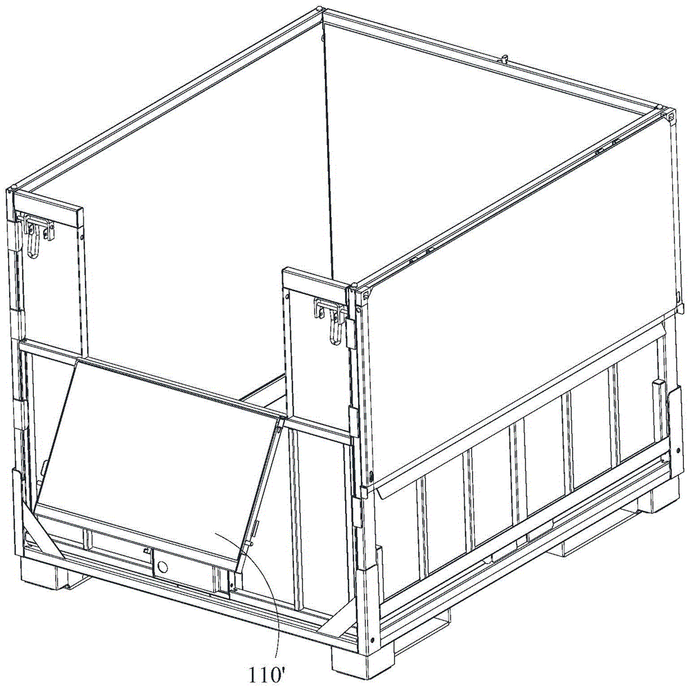
[0049] Since the lock does not protrude from the outer contour of the end wall in the opened state, it can avoid damage to the parts when the end wall is opened or folded. Moreover, the locking plate is kept in the locked state or the ...

no. 2 example

[0059] The difference between this embodiment and the first embodiment is that, if Figure 20 As shown, the inner edge S2 of the second locking hole 130 is provided with a vertical plate 140 that enters the interior of the second connecting beam 110 and extends to the bottom surface of the second connecting beam 110, and defines the space between the vertical plate 140 and the outer edge S3 of the locking plate 11. The rotation space allows the lock plate 11 to rotate freely in the rotation space without being interfered by the inner edge S2 of the second lock hole 130 .

no. 3 example

[0061] The difference between this embodiment and the first embodiment is that, if Figure 21 , 22 As shown, on the side of the lock plate 11 facing the cover plate 120, a protrusion 114 is protruded from the upper end of the lock plate 11. The protrusion 114 contacts the outer surface of the inner wall of the second connecting beam 110, and the protrusion 114 The height is greater than or equal to the distance d between the outer surface of the inner wall of the second connecting beam and the inner edge of the second locking hole, so that there is a distance between the locking plate 11 and the inner side of the second connecting beam 110, and will not be in contact with the second connecting beam 110 during rotation. The inner edges S2 of the two locking holes 130 interfere.


PUM


Abstract

The invention provides a lock and a tray box. The lock is used for locking a first component and a second component of the tray box, and the first component and the second component are adjacent. The lock comprises a lock plate, a pin shaft and an elastic part, wherein a hook part is arranged at the upper end of the lock plate, and a through hole is formed below the hook part; one end of the pin shaft penetrates through the through hole and is fixed to the second component; the pin shaft is sleeved with the elastic part, the elastic part is pressed on the lock plate, and the lock plate rotates around the pin shaft to be in a locking state or open state. In the locking state, the hook part is locked with the first component. In the open state, the surface of the lock plate does not protrude out of the outline of the second component. Moreover, under the elastic function of the elastic part, the lock plate is kept in the locking state or the open state. The lock does not protrude out of the outline of the end wall where the lock is located in the open state, so that damage to the part when the end wall is opened or folded is avoided. The lock is simple in structure, low in cost and convenient to operate.

Description

technical field [0001] The invention relates to a lock for a pallet box, in particular to a lock for connecting the top cover and the end wall of the pallet box. Background technique [0002] Pallet boxes generally consist of a chassis, two end walls, two side walls and a top cover. At present, there are many forms of pallet boxes, such as figure 1 , 2 Pallet box shown with half-folding doors. In order to reduce the cost of logistics packaging, the way of adding liner bags to pallet boxes is commonly used to load fluid goods such as liquids, granules or powdery solids. In order to facilitate unloading, a half-fold door 110' is usually set on one end wall of the pallet box and the lower discharge port. The half-fold door 110' is connected with the top cover 200 through a hook lock 300. When installing the liner bag, the operator rotates the hook lock 300, opens the half-fold door 110', and turns it down, then bends down and penetrates into the box, arranges the liner bag...

Claims


Application Information

Patent Timeline
IPC IPC(8): B65D19/06B65D55/10
Inventor 苏继军刘春良
Owner CHINA INTERNATIONAL MARINE CONTAINERS (GROUP) CO LTD
Why Eureka
Try Eureka