A split reduction clutch housing

A deceleration clutch, split-type technology, applied in the field of washing machines, can solve the problems of unfavorable manufacturing and installation, high cost, etc., and achieve the effect of easy disassembly and replacement, easy assembly, and cost reduction

Active Publication Date: 2019-01-22
QINGDAO HAIER WASHING MASCH CO LTD
View PDF6 Cites 0 Cited by
  • Summary
  • Abstract
  • Description
  • Claims
  • Application Information

AI Technical Summary

Problems solved by technology

This installation method is not suitable for the deceleration clutch of a large-capacity washing machine, mainly because, due to the large volume of the deceleration clutch of a large-capacity washing machine, if the shell is made of one piece, in order to meet the strength requirements of the installation, a very thick shell wall , which is not only costly, but also not conducive to manufacturing and installation

Method used


Image

  • A split reduction clutch housing
  • A split reduction clutch housing
  • A split reduction clutch housing

Examples


Embodiment 1

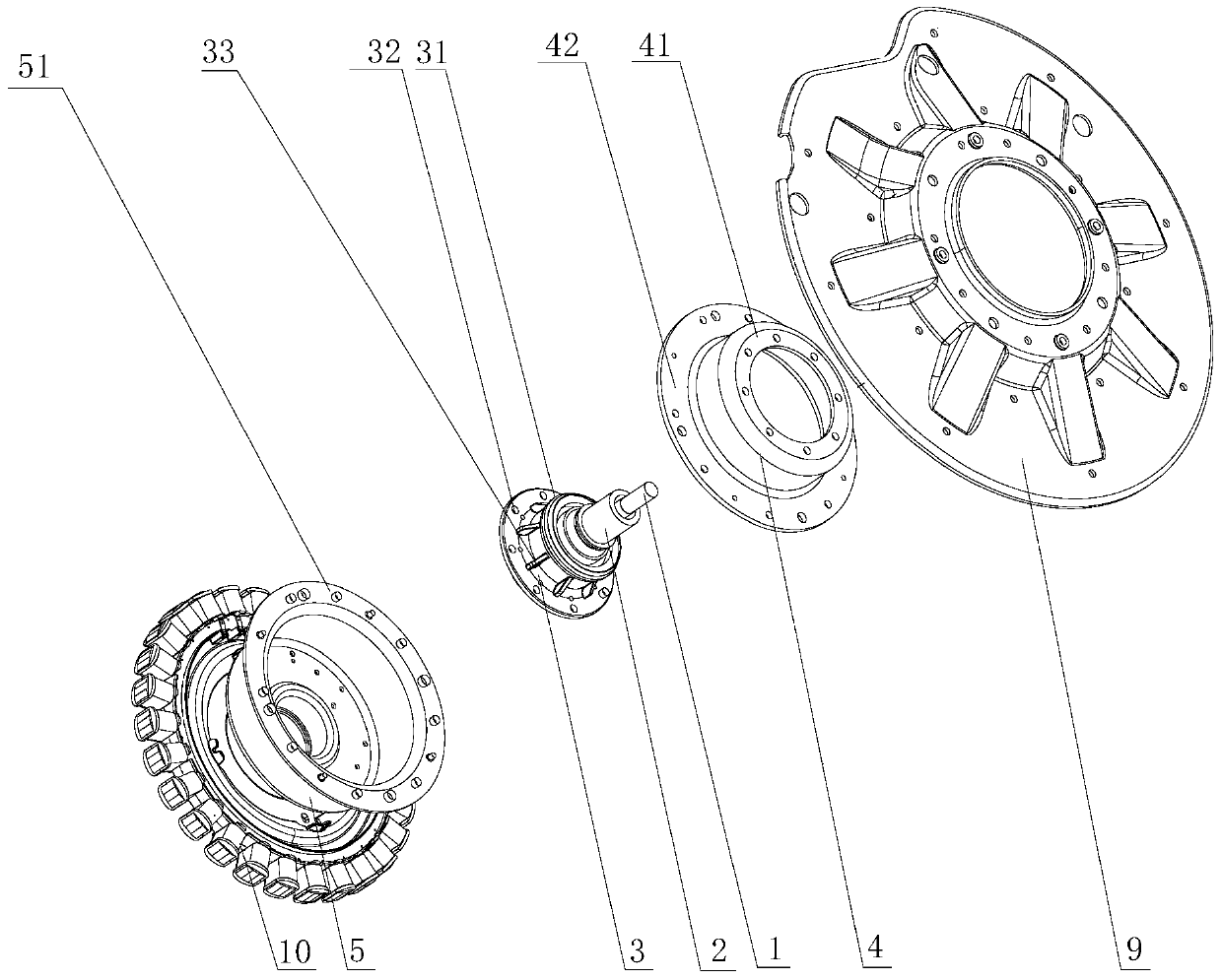
[0065] Such as Figure 3-5As shown, the lower end of the lower end cover 5 of the present invention is provided with a clutch mechanism, and the clutch mechanism includes an upper fixed plate 15, a clutch sleeve 17 that can slide up and down and a lower dehydration plate 19, and the clutch sleeve 17 slides up and down and is respectively fixed with the upper The disc 15 and the lower dehydration disc 19 are meshed and connected to realize the conversion of washing and dehydration working conditions; the upper fixed disc 15 and the stator 10 of the motor are fixedly connected to the lower end surface of the lower end cover 5 respectively, and the stator 10 is connected to the Lower end cover 5 For fixed connection, the connecting piece 24 is an independent component.

[0066] The clutch device of the present invention is mainly used for large-capacity washing machines, and the capacity of the large-capacity washing machine of the present invention is above 15-20 kg, so the clu...

Embodiment 2

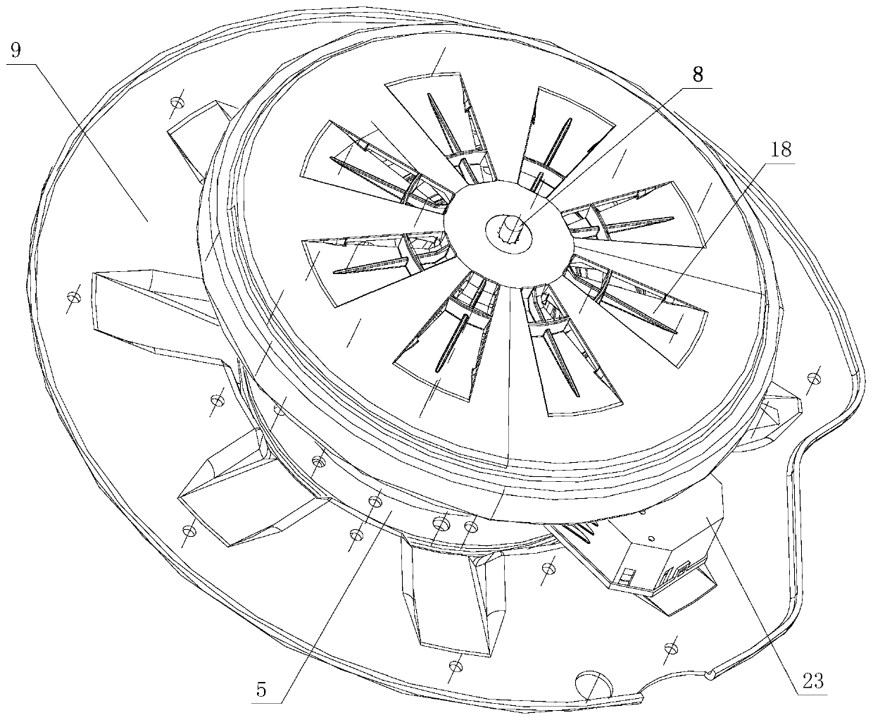
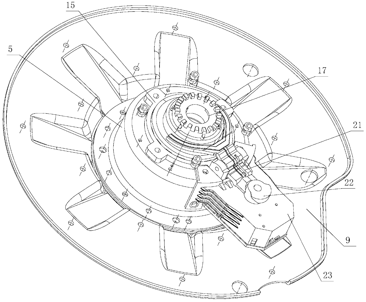
[0077] The clutch device of the present invention is driven by the clutch driving device, and the clutch driving device drives the clutch sleeve 17 to move up and down to realize the clutch. Such as Figure 2-6 As shown, the clutch driving device of the present invention includes a driving motor 25 , a driving wheel 22 and a fork lever 21 . The shift fork lever 21 is a lever structure, the middle part is provided with a fixed fulcrum, the head is a shift fork 211, and the tail is a driving end 212 supported on the driving wheel 22. A boss 171 is provided on the outer circumference of the clutch sleeve 17, and a return spring 16 is provided between the upper surface of the boss 171 and the lower end cover 5 of the casing to provide a sliding force to the clutch sleeve 17; the lower surface of the boss 171 and the shift fork The head of the rod 21 is in contact with the shift fork 211 , and the shift fork rod 21 provides a variable lifting force for the clutch sleeve 17 . The ...

Embodiment 3

[0079] Such as Figure 3 to Figure 8 As shown, a deceleration clutch clutch driving device described in this embodiment includes a driving motor 25, a driving wheel 22 and a shift fork lever 21, and the driving wheel 22 is installed on the motor shaft of the driving motor 25, and the circumference of the driving wheel 22 is provided with supports The supporting surface has a height difference in the axial direction. The shift fork lever 21 is a lever structure with a fixed fulcrum in the middle. The head of the shift fork lever 21 is a shift fork 211. The shift fork 211 is located below the clutch sleeve 17, and the return spring 20 together to control the up and down movement of the clutch sleeve 17, the tail of the shift fork lever 21 is the driving end 212, and the driving end 212 is provided with a sliding contact surface, which is slidably matched with the supporting surface; the drive motor 25 drives the driving wheel 22 to rotate, and the tail of the shift fork lever 21 ...


PUM


Abstract

The invention provides a separated-type decelerating clutch outer shell, which comprises an upper end cover, a lower end cover and a mounting plate, wherein the upper end cover and the lower end cover are connected to form a chamber; a gear wheel box of a decelerating clutch is set in the chamber; the upper end cover is separated-type structure; the upper end cover comprises a cover body of the upper end cover and an upper end cover main body; a lower portion of the upper end cover main body is connected to the lower end cover; an upper end portion of the upper end cover main body is connected to the cover body of the upper end cover; and the upper end cover main body is fixedly mounted on the mounting plate. According to the invention, the decelerating clutch outer shell with the separated-type structure is adopted, thus solving the problem that the existing decelerating clutch is not suitable for a large capacity washer; the breakage produced due to centralized stress on a connecting position between the decelerating clutch outer shell and an input shaft or an output shaft; and the stability and the reliability of the power transmission of the large capacity washer is ensured.

Description

technical field [0001] The invention relates to the field of washing machines, in particular to a split type deceleration clutch housing. Background technique [0002] As a daily household appliance, washing machine liberates people from the labor of doing laundry, so it is very popular among users. However, with the rapid development of society, people have higher and higher requirements for washing machines, including people's higher and higher requirements for the capacity of washing machines. Therefore, large-capacity washing machines are thus produced. [0003] Since the washing capacity of the large-capacity washing machine is larger, more power is needed to drive the washing, so a more powerful motor is required to provide power. In order to ensure the stability and reliability of power transmission, the length and diameter of the input shaft and output shaft of the deceleration clutch of the large-capacity washing machine must be increased accordingly. In order to m...

Claims


Application Information

Patent Timeline
Patent Type & Authority Patents(China)
IPC IPC(8): D06F37/40
Inventor 杨林张刚金田云龚孟虎
Owner QINGDAO HAIER WASHING MASCH CO LTD
Why Eureka
Try Eureka