Injection molding mold for micro motor framework

A technology of injection molding and micro motor, which is applied in the field of mold manufacturing, can solve the problems of high injection pressure, poor overall effect, small wall thickness, etc., and achieve the effect of improving product molding quality, reducing molding process difficulty, and improving overall functions

Pending Publication Date: 2022-03-01
嘉兴横河汽车电器有限公司
View PDF0 Cites 0 Cited by
  • Summary
  • Abstract
  • Description
  • Claims
  • Application Information

AI Technical Summary

Problems solved by technology

[0002] like Figure 4 As shown, it is a structural schematic diagram of an existing micro-motor skeleton, which includes a ring-shaped skeleton body 100, and twelve vertical baffles distributed in a circular array at equal intervals are arranged on the end face of the skeleton body 100. 101, the cross-section of the vertical baffle 101 is C-like, the wall thickness is small, the injection molding process requires high injection pressure for raw materials, and there is still a high probability of output under the condition of maintaining a high injection pressure Unqualified product, poor overall effect

Method used


Image

  • Injection molding mold for micro motor framework
  • Injection molding mold for micro motor framework
  • Injection molding mold for micro motor framework

Examples


Embodiment 1

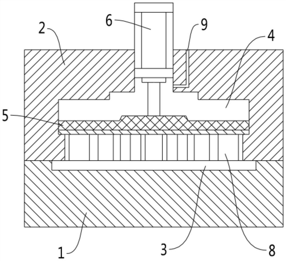
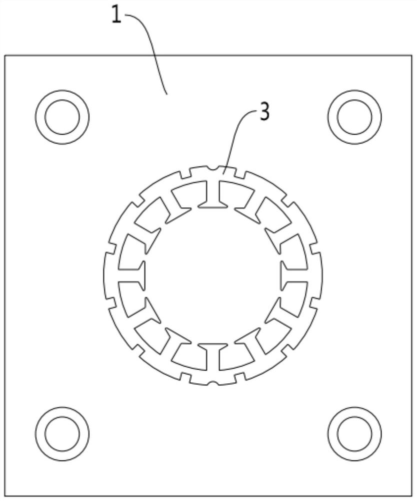
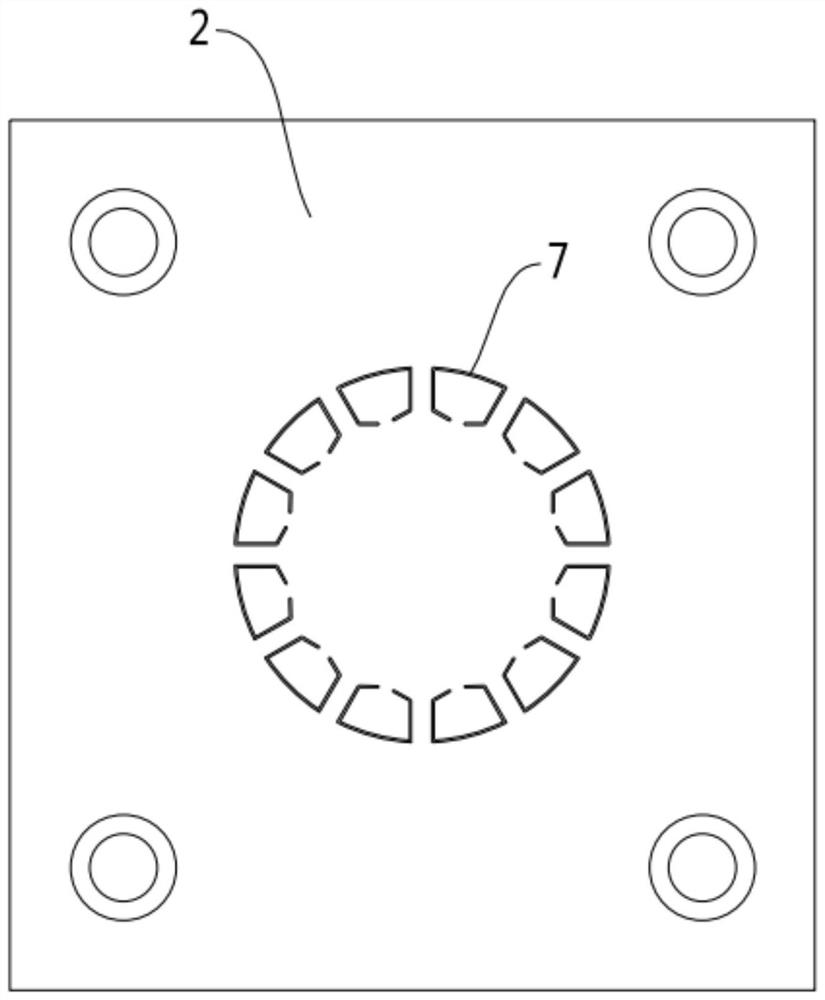
[0015] see Figures 1 to 3 As shown, a micro-motor skeleton injection molding mold involved in this embodiment includes a lower mold base 1 and an upper mold base 2 arranged above the lower mold base 1, and a notch is provided on the lower mold base 1. The forming groove 3 on the upper end surface, the inside of the upper mold base 2 is provided with a piston cavity 4, the piston cavity 4 is slidingly connected with a piston 5, and the piston 5 is provided with a linear reciprocating mechanism 6 for controlling its vertical up and down movement. The upper mold base 2 is provided with a blocking plate forming channel 7, one end of the blocking plate forming channel 7 is connected to the forming groove 3, and the other end is connected to the piston cavity 4, and one end of the blocking plate forming channel 7 is slidably connected to the piston 5 Connected, the other end of which is flush with the lower end surface of the upper die base 2, the profiled baffle forming block 8, t...

Embodiment 2

[0019] see Figures 1 to 3 As shown, the injection molding mold for a micro-motor skeleton involved in this embodiment is further set up on the basis of Embodiment 1, and a heat insulation plate is provided between the piston 5 and the profiling block forming block 8 10 , the heat insulation plate 10 is fixed on the piston 5 , and the profiling baffle forming block 8 is fixed on the heat insulation plate 10 .

[0020] In this embodiment, the setting of the heat shield 10 is used for heat insulation, avoiding the concentrated transfer of heat energy in the plastic raw material melted by high temperature to the piston 5, and preventing the excessive expansion of the piston 5 due to excessive temperature, which affects the upper and lower sides. slide.

[0021] The micro-motor skeleton injection molding mold involved in the present invention can still complete high-quality product molding operations under the condition of relatively low injection pressure, which reduces the diff...


PUM


Abstract

The micro motor framework injection molding mold comprises a lower mold base and an upper mold base arranged above the lower mold base, a forming groove with a notch formed in the upper end face of the lower mold base is formed in the lower mold base, a piston cavity is formed in the upper mold base, and a piston is slidably connected into the piston cavity; the piston is provided with a linear reciprocating motion mechanism controlling the piston to vertically move up and down, the upper die base is provided with a blocking piece forming channel, one end of the blocking piece forming channel is communicated with the forming groove, and the other end of the blocking piece forming channel is communicated with the piston cavity. A profiling separation blade forming block is slidably connected into the separation blade forming channel, one end of the profiling separation blade forming block is connected with the piston, the other end of the profiling separation blade forming block is flush with the lower end face of the upper die base, and a balance air channel enabling the piston cavity to be communicated with the outside is further formed in the upper die base. The injection molding mold has the characteristics of novel structure and high molding quality, and is complete in overall function and high in practicability.

Description

technical field [0001] The invention relates to the technical field of mold manufacturing, more specifically, it relates to a micro-motor frame injection molding mold. Background technique [0002] Such as Figure 4 As shown, it is a structural schematic diagram of an existing micro-motor skeleton, which includes a ring-shaped skeleton body 100, and twelve vertical baffles distributed in a circular array at equal intervals are arranged on the end face of the skeleton body 100. 101, the cross-section of the vertical baffle 101 is C-like, the wall thickness is small, the injection molding process requires high injection pressure for raw materials, and there is still a high probability of output under the condition of maintaining a high injection pressure Substandard products, the overall effect is not good. Accordingly, the present invention proposes a micro-motor frame injection mold. Contents of the invention [0003] The object of the present invention is to overcome th...

Claims


Application Information

Patent Timeline
IPC IPC(8): B29C45/26B29C45/34B29C45/56
CPCB29C45/2626B29C45/34B29C45/56
Inventor 李志清
Owner 嘉兴横河汽车电器有限公司
Why Eureka
Try Eureka