
A two-phase distributive dry evaporator

A dry evaporator and phase distribution technology, applied in the direction of evaporator/condenser, refrigeration components, refrigerators, etc., can solve the problem that gas-liquid two-phase refrigerant is difficult to distribute the evaporation tube, the area of ​​the evaporation tube is insufficient, and the area of ​​the evaporation tube Waste and other problems, to achieve the effect of solving low heat transfer efficiency, guaranteeing distribution uniformity, and improving heat transfer efficiency

Active Publication Date: 2018-02-27
ZHEJIANG YINGGU ENERGY SAVING EQUIP
View PDF8 Cites 0 Cited by
  • Summary
  • Abstract
  • Description
  • Claims
  • Application Information

AI Technical Summary

Problems solved by technology

But it also has the following defects: (1) It is difficult for the gas-liquid two-phase refrigerant to be evenly distributed into each evaporator tube; (2) The gaseous refrigerant has the characteristic of naturally gathering upwards, so the upper part of the distribution chamber is basically a gas (3) At the bottom of the distribution chamber, the liquid refrigerant competes for the limited inlet of the evaporator tube, resulting in a relatively insufficient area of ​​the evaporator tube, resulting in a decrease in heat transfer efficiency, and even part of the refrigerant is not fully evaporated The liquid refrigerant is directly sucked into the compressor, causing the compressor to run with liquid and damage the compressor

Method used


Image

  • A two-phase distributive dry evaporator

Examples


Embodiment Construction

[0021] The present invention will be further described below in conjunction with the accompanying drawings.

[0022] This specific embodiment is an explanation of the present invention, not a limitation of the present invention. Any modifications made by those skilled in the art after reading the description of the present invention, as long as they are within the scope of the claims, will be protected by the patent law. .

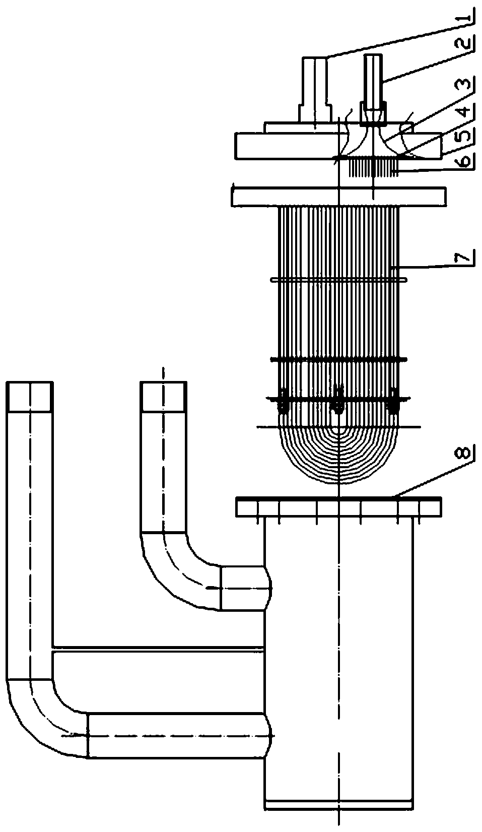
[0023] Such as figure 1 As shown, a two-phase distributive dry evaporator includes a cylinder body 8 and an integrated cover 5. A number of evaporation tubes 7 are arranged inside the cylinder body 8, and the evaporation tubes 7 are horizontal U-shaped tubes. One end is the inlet and the other end is the outlet. The gas-liquid two-phase refrigerant enters from the inlet, and the refrigerant is converted into a gaseous state. The conversion process is a heat exchange process. After heat exchange, the gaseous refrigerant exits from the outlet. Usually, th...


PUM


Abstract

The invention relates to a two-phase distribution dry-type evaporator and belongs to the technical field of heat exchange. The two-phase distribution dry-type evaporator comprises a plurality of evaporating pipes. Inlets and outlets of the evaporating pipes are not uniform in height position, wherein the inlets are formed in the low positions while the outlets are formed in the high positions. The two-phase distribution dry-type evaporator further comprises a siphon distribution cavity, two-phase refrigerating fluid enters the siphon distribution cavity from an inlet of the siphon distribution cavity, and an outlet of the siphon distribution cavity is communicated with the evaporating pipes in a closed manner. By the adoption of the siphon distribution cavity, the gas-liquid phase refrigerating fluid is evenly distributed, and the problem of low heat exchange efficiency in the prior art is solved.

Description

technical field [0001] The invention relates to a dry evaporator, in particular to a two-phase distributive dry evaporator, which belongs to the technical field of heat exchange. Background technique [0002] As a traditional dry shell-and-tube heat exchanger, dry evaporators account for a large proportion of the market, especially dry evaporators for low-temperature refrigeration and freezing chillers and air-cooled units. The traditional dry evaporator consists of a shell, a cover, a tube box, a tube sheet and multiple evaporating tubes. Chilled water flows between the shell and the evaporating tubes, and the refrigerant flows inside the evaporating tubes. It can not only save the charging amount of refrigerant, but also has good oil return performance. But it also has the following defects: (1) It is difficult for the gas-liquid two-phase refrigerant to be evenly distributed into each evaporator tube; (2) The gaseous refrigerant has the characteristic of naturally gather...

Claims


Application Information

Patent Timeline
Patent Type & Authority Patents(China)
IPC IPC(8): F25B39/02
Inventor 罗众锋年介斌李隆根
Owner ZHEJIANG YINGGU ENERGY SAVING EQUIP
Learn More