Eureka AIR delivers breakthrough ideas for toughest innovation challenges, trusted by R&D personnel around the world.

Air drying device of row lines

An air-drying device and line-running technology, which is applied in the direction of drying gas arrangement, drying, and dryers, can solve problems such as inconvenient operation, disorderly blowing direction, and non-concentrated wind, so as to improve air-drying efficiency, solve problems such as easy disconnection, Ease of threading

Active Publication Date: 2016-01-13
苏州市吴江神州双金属线缆有限公司
View PDF7 Cites 1 Cited by
  • Summary
  • Abstract
  • Description
  • Claims
  • Application Information

AI Technical Summary

Problems solved by technology

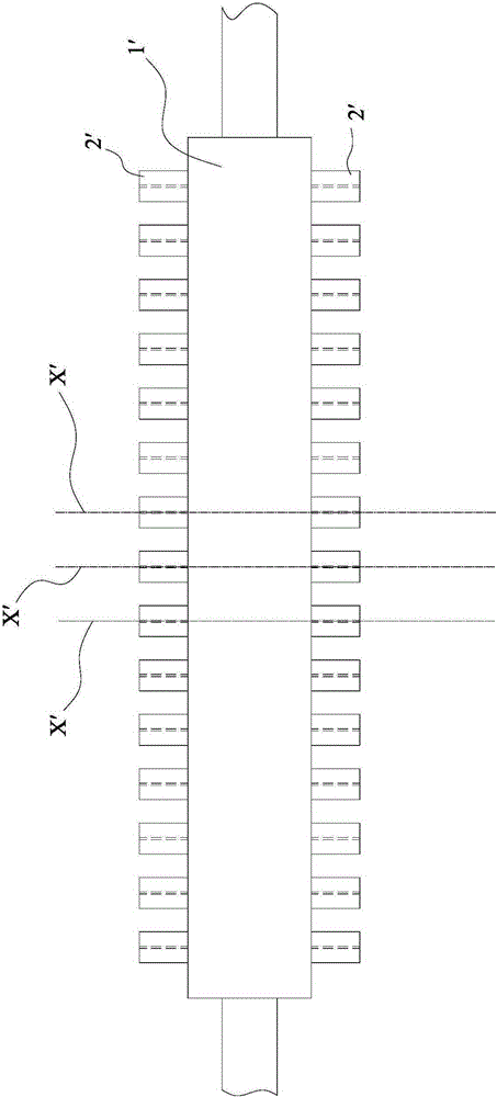
[0003] Yet above-mentioned air-drying device, it has had the following obvious defectives:
[0004] 1) The wind flows in the air-drying pipe and impacts the running lines. Once the wind is too strong, it is easy to cause friction or entanglement between rows of running lines in the air-drying pipe, which directly leads to the breaking of the running lines.
[0005] 2) The blowing direction of the wind in the air-drying pipe is chaotic, causing the wind force to be inconcentrated and unable to achieve the expected air-drying effect
[0006] 3) Since the conduits on both sides are set in one-to-one correspondence, when each row line passes through one of the conduits, and then passes through the corresponding other conduit, it is difficult to make sure that the position of the line head cannot be seen. The line head passes through the latter's conduit, which brings great inconvenience to the actual operation

Method used


Image

  • Air drying device of row lines
  • Air drying device of row lines
  • Air drying device of row lines

Examples


Embodiment Construction

[0024] Preferred embodiments of the present invention will be described in detail below in conjunction with the accompanying drawings.

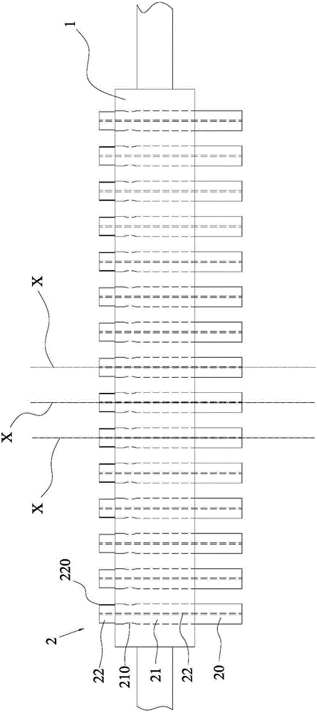
[0025] Such as figure 2 and image 3 As shown, the line air-drying device provided in this embodiment includes an air-drying pipe 1 connected to an air inlet pipe at one end and an air-out pipe at the other end; 2. In particular, each wire conduit 2 passes through both sides of the air-drying pipe 1 respectively, and the junction of the two is sealed and connected, and the wire pipe 2 passing through the air-drying pipe 1 is divided into three sections, and the three sections are respectively The middle section 21 located inside the air-drying pipe 1, and the incoming line section 20 and the outgoing line section 22 respectively located on both sides of the air-drying pipe 1, wherein the middle section 21 is provided with an air guide hole 210 communicating with the inner line channel 23 of the wire duct 2 , the wind located in the air dry...


PUM


Abstract

The invention relates to an air drying device of row lines. The air drying device comprises an air drying pipe and a plurality of line guide pipes. One end of the air drying pipe is connected with an air inlet pipe, and the other end of the air drying pipe is connected with an air outlet pipe. The line guide pipes are arranged in the direction intersecting with the air drying pipe. Each line guide pipe penetrates the two sides of the air drying pipe. The joints of each line guide pipe and the two sides of the air drying pipe are connected in a sealed manner. Each line guide pipe penetrating the air drying pipe is divided into three sections, namely, a middle section located in the air drying pipe, a line inlet section and a line outlet section, wherein the line inlet section and the line outlet section are located on the two sides of the air drying pipe respectively, an air guide hole communicated with a row line passageway in the line guide pipe is formed in the middle section, air located in the air drying pipe is led into the row line passageway through the air guide hole to dry the corresponding row line located in the row line passageway. By means of the air drying device, on one hand, all the row lines entering the air drying pipe are separated, friction or winding between every two adjacent row lines is prevented, and the problem that line breakage is prone to happening is solved; on the other hand, wind can be conveniently guided to the surfaces of the row lines in a concentrated manner, and therefore the air drying efficiency is improved; and in addition, the structure is simple, and threading of the row lines is facilitated.

Description

technical field [0001] The invention relates to a line air-drying device. Background technique [0002] As we all know, after the heat treatment of the line, the water on the surface needs to be dried to realize the processing of the line. At present, air drying devices such as figure 1 As shown, it mainly includes an air-drying pipe 1' connected at one end to the air-intake pipe and the other end to the air-outlet pipe; wire ducts 2' arranged side by side on both sides of the air-drying pipe 1' and connected to the air-drying pipe 1', Wherein the conduits 2' located on both sides are arranged in one-to-one correspondence, and each row line X' is imported from one conduit 2' into the air-drying pipe 1', and then the row is exported through another conduit 2', imported and exported During the process, the wind flows in the air-drying pipe 1', thereby air-drying the surface of the line. [0003] Yet above-mentioned air-drying device, it has had the following obvious defecti...

Claims


Application Information

Patent Timeline
Patent Type & Authority Applications(China)
IPC IPC(8): F26B13/24F26B21/00
Inventor 张建峰
Owner 苏州市吴江神州双金属线缆有限公司
Why Eureka
Eureka Blog
Learn More