Transparent displayer

A transparent display and light guide plate technology, which can be used in static indicators, instruments, nonlinear optics, etc., and can solve the problems of low energy consumption and transparent displays

Inactive Publication Date: 2016-01-13
WUHAN CHINA STAR OPTOELECTRONICS TECH CO LTD
View PDF5 Cites 20 Cited by
  • Summary
  • Abstract
  • Description
  • Claims
  • Application Information

AI Technical Summary

Problems solved by technology

[0004] The technical problem to be solved by the present invention is to provide a transparent display with low energy consumption when displaying picture images

Method used


Image

  • Transparent displayer
  • Transparent displayer
  • Transparent displayer

Examples


Embodiment Construction

[0024] The following will clearly and completely describe the technical solutions in the embodiments of the present invention with reference to the drawings in the embodiments of the present invention.

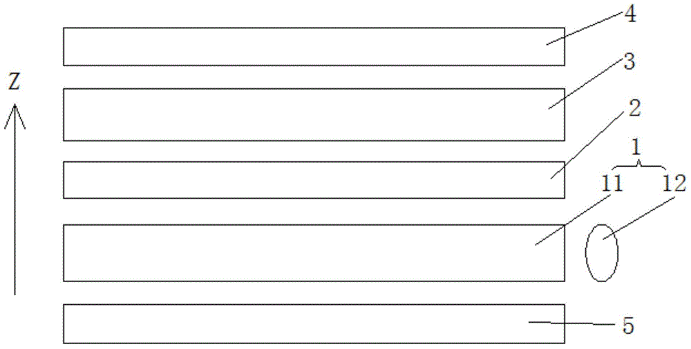
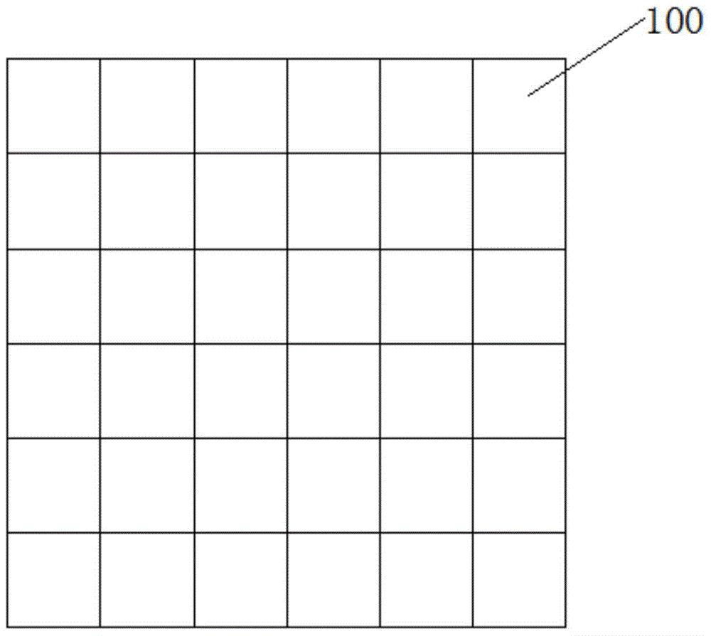
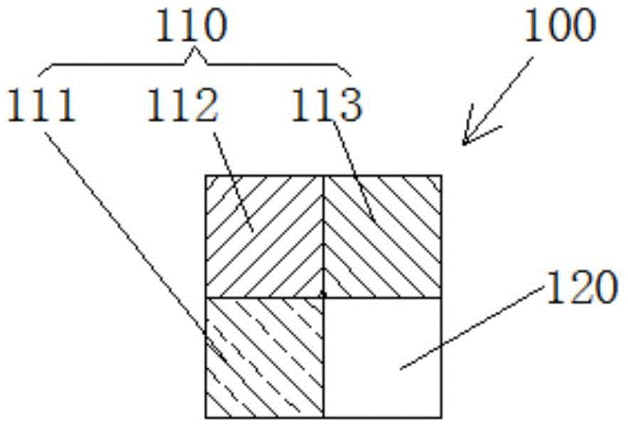
[0025] see Figure 1 to Figure 3 , Embodiment 1 of the present invention provides a transparent display, including along the image display direction Z (such as figure 1 shown in the Z direction), the backlight module 1 , the array substrate 2 , the liquid crystal layer 3 and the color filter substrate 4 are sequentially stacked. Such as figure 2 As shown, the color filter substrate includes a plurality of adjacent pixel regions 100 . Such as image 3 As shown, each of the pixel areas 200 includes a display area 110 and a transparent area 120, and the display area 110 includes a red (R) sub-pixel area 111, a green sub-pixel area 112 and a blue (B) sub-pixel area 112. ) sub-pixel regions 113, each of the transparent regions 120 includes a white (W) sub-pixel region. The ar...


PUM


Abstract

The invention discloses a transparent displayer comprising a backlight module, an array substrate, a liquid crystal layer and a color film substrate which are sequentially stacked in an image display direction. The color film substrate comprises a plurality of adjacent pixel areas, each pixel area comprises a display area and a transparent area, each display area comprises a red sub-pixel area, a green sub-pixel area and a blue sub-pixel area, each transparent area comprises a white sub-pixel area, the array substrate is provided with a plurality of thin film transistors which are distributed in an array mode, and the thin film transistors are in one-to-one correspondence with the red sub-pixel areas, the green sub-pixel areas, the blue sub-pixel areas and the white sub-pixel areas of the color film substrate. The energy consumption of the transparent displayer is low when a screen image is displayed.

Description

technical field [0001] The invention relates to the technical field of transparent display, in particular to a transparent display. Background technique [0002] A transparent display means that the display itself has a certain degree of light penetration, allowing users to clearly see the background behind the display when watching the display. Therefore, the transparent display is suitable for application in building windows, automobile windows, shop windows, and the like. [0003] Existing transparent displays often include a transparent area and a display area at the same time. When the transparent display displays a picture, it can simultaneously display a background image and a picture image. However, the display quality of the picture image in this display mode is poor. In order to solve the problem of poor image display quality, the industry further proposes to make the transparent area of ​​the transparent display area in a dark state in the real image mode to ensu...

Claims


Application Information

Patent Timeline
Patent Type & Authority Applications(China)
IPC IPC(8): G02F1/1335G02F1/1368G02F1/13357G02F1/133
CPCG02F1/13306G02F1/1335G02F1/133615G02F1/1368G09G3/2003G09G2300/0452G09G3/32
Inventor 唐岳军
Owner WUHAN CHINA STAR OPTOELECTRONICS TECH CO LTD
Why Eureka
Try Eureka